
Machining method for rotating shaft bearing bases

A technology for a shaft support seat and a processing method, which is applied in the directions of bearings, metal processing equipment, metal processing machinery parts, etc., can solve the problems of low production efficiency and difficult clamping, and achieve high production efficiency, simple clamping and convenient operation. Effect

Inactive Publication Date: 2016-10-12
WUZHOU OKA OPTICAL INSTR
View PDF10 Cites 2 Cited by
  • Summary
  • Abstract
  • Description
  • Claims
  • Application Information

AI Technical Summary

Problems solved by technology

[0003] The technical problem to be solved by the present invention is to provide a processing method for the supporting seat of the rotating shaft, so as to solve the problems of difficulty in fitting and clamping the inclined surfaces on the two ear plates of the supporting seat of the rotating shaft and low production efficiency

Method used


Image

  • Machining method for rotating shaft bearing bases
  • Machining method for rotating shaft bearing bases
  • Machining method for rotating shaft bearing bases

Examples


Embodiment Construction

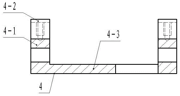
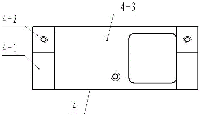
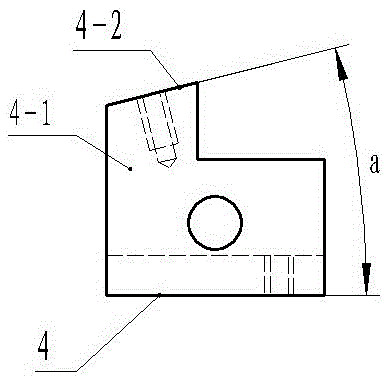
[0018] The present invention will be described in further detail below in conjunction with accompanying drawing embodiment:

[0019] Such as figure 1 , figure 2 , image 3 The rotating shaft supporting seat shown includes two ear plates 4-1 respectively connected to the two ends of the support plate 4-3. The two ear plates 4-1 are arranged opposite to each other and protrude upwards. The upper end is provided with an inclined surface 4-2 inclined to the outside and a plane parallel to the bottom surface of the support plate 4-3, the angle between the inclined surface 4-2 and the bottom surface of the support plate 4-3 is 14 degrees, and the upper end of the support plate 4-3 Have square through hole; The present embodiment is to process inclined plane 4-2.

[0020] Such as Figure 4 , Figure 5 , Figure 6 The shown milling fixture for a rotating shaft support seat includes a base 1, and the base 1 is provided with two positioning slanting blocks 1-1 oppositely arranged...


PUM


Abstract

The invention discloses a machining method for rotating shaft bearing bases, and relates to the technical field of machining. A rotating shaft bearing base milling clamp is used for conducting machining and comprises a base. The base is provided with two positioning inclined blocks which are oppositely arranged. The high portions of the two positioning inclined blocks are connected. Each positioning inclined block has a positioning face. The included angles between the positioning faces and the bottom faces of the positioning inclined blocks are alpha. Pressing plates are connected to the positioning faces through bolts. The two ends of each positioning inclined block are each provided with a limiting boss. The low portions of the positioning inclined blocks are connected with limiting blocks. The machining steps of the machining method include the first step of clamp installation, the second step of workpiece installation, the third step of face milling and the fourth step of rotating shaft bearing base detachment. Compared with the prior art, the two rotating shaft bearing bases can be clamped at a time for inclined face machining, the production efficiency is high, the rotating shaft bearing base clamping is easy, and operation is convenient.

Description

technical field [0001] The invention relates to the technical field of mechanical processing, in particular to a processing method for a rotating shaft support seat. Background technique [0002] The rotating shaft supporting seat of the transmission mechanism of the microscope objective lens group is a part used to install the rotating shaft. There is a rotating shaft supporting seat such as figure 1 , figure 2 , image 3 As shown, the rotating shaft supporting seat 4 includes two ear plates 4-1 respectively connected to the two ends of the support plate 4-3. The two ear plates 4-1 are arranged opposite to each other and protrude upwards. There is an inclined surface 4-2 inclined to the outside and a plane parallel to the bottom surface of the support plate 4-3, the angle between the inclined surface 4-2 and the bottom surface of the support plate 4-3 is 14 degrees, and the opening on the support plate 4-3 There are square through holes. When processing the slopes on t...

Claims


Application Information

Patent Timeline
IPC IPC(8): B23C3/00B23Q3/06
CPCB23C3/00B23Q3/062
Inventor 张景华
Owner WUZHOU OKA OPTICAL INSTR
Features
  • Generate Ideas
  • Intellectual Property
  • Life Sciences
  • Materials
  • Tech Scout
  • Unparalleled Data Quality
  • Higher Quality Content
  • 60% Fewer Hallucinations
Learn More