Supercharge Your Innovation With Domain-Expert AI Agents!

a pneumatic punch

A technology of pneumatic punching machines and cylinders, applied in punching machines, presses, manufacturing tools, etc., can solve the problems of limited stroke height, low safety factor, insufficient punching force, etc., to increase punching force, high punching efficiency, and large punching force. Effect

Active Publication Date: 2018-08-21
艾佛森(深圳)科技有限公司
View PDF5 Cites 0 Cited by
  • Summary
  • Abstract
  • Description
  • Claims
  • Application Information

AI Technical Summary

Problems solved by technology

The direct pressure pneumatic punching machine is cheap, but the frame is rough, the precision is low, and the punching force is not enough; the small electric punching machine is fast enough, but the safety factor is low and the stroke height is limited

Method used


Image

  • a pneumatic punch
  • a pneumatic punch
  • a pneumatic punch

Examples


Embodiment Construction

[0018] The technical solutions of the present invention will be further described below in conjunction with the accompanying drawings and through specific implementation methods.

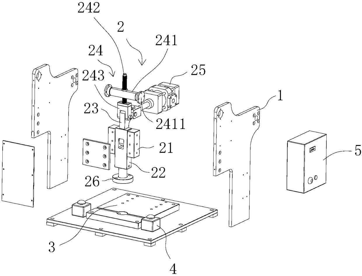
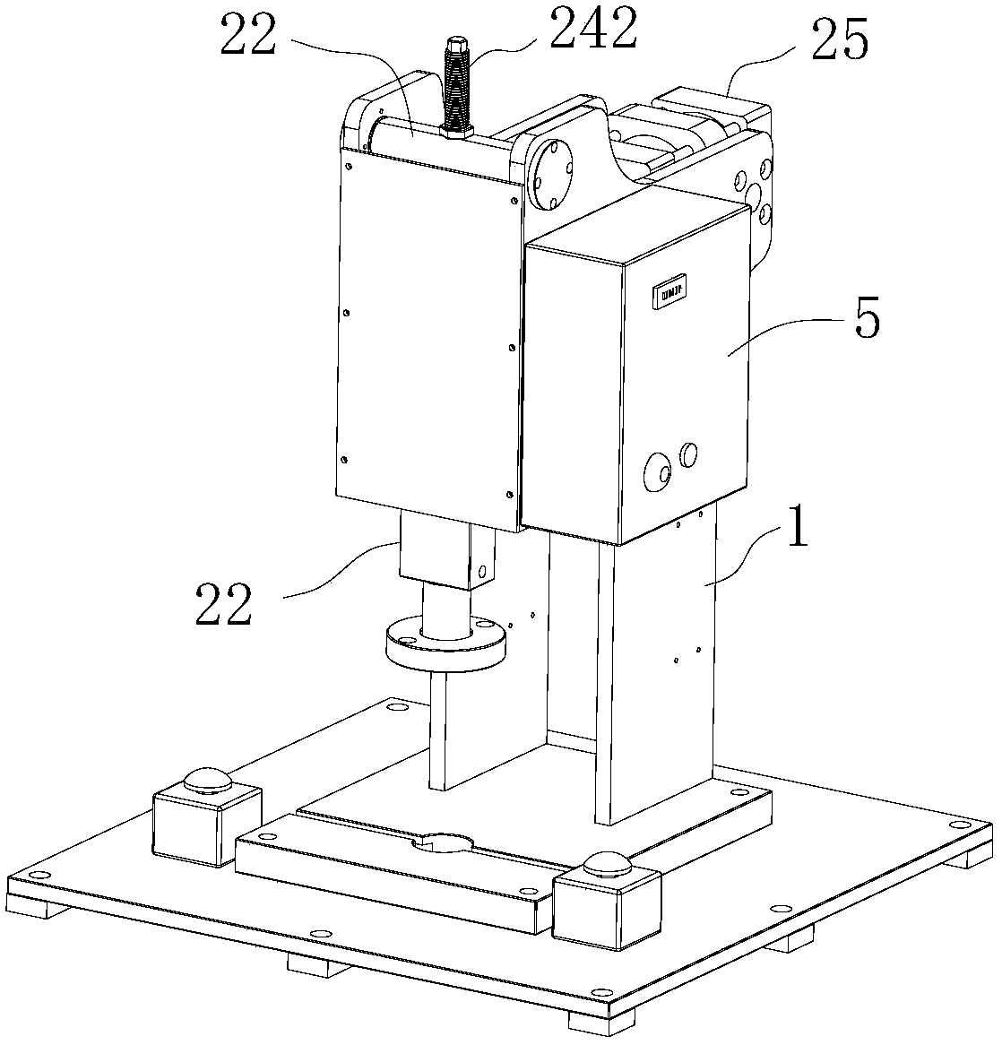
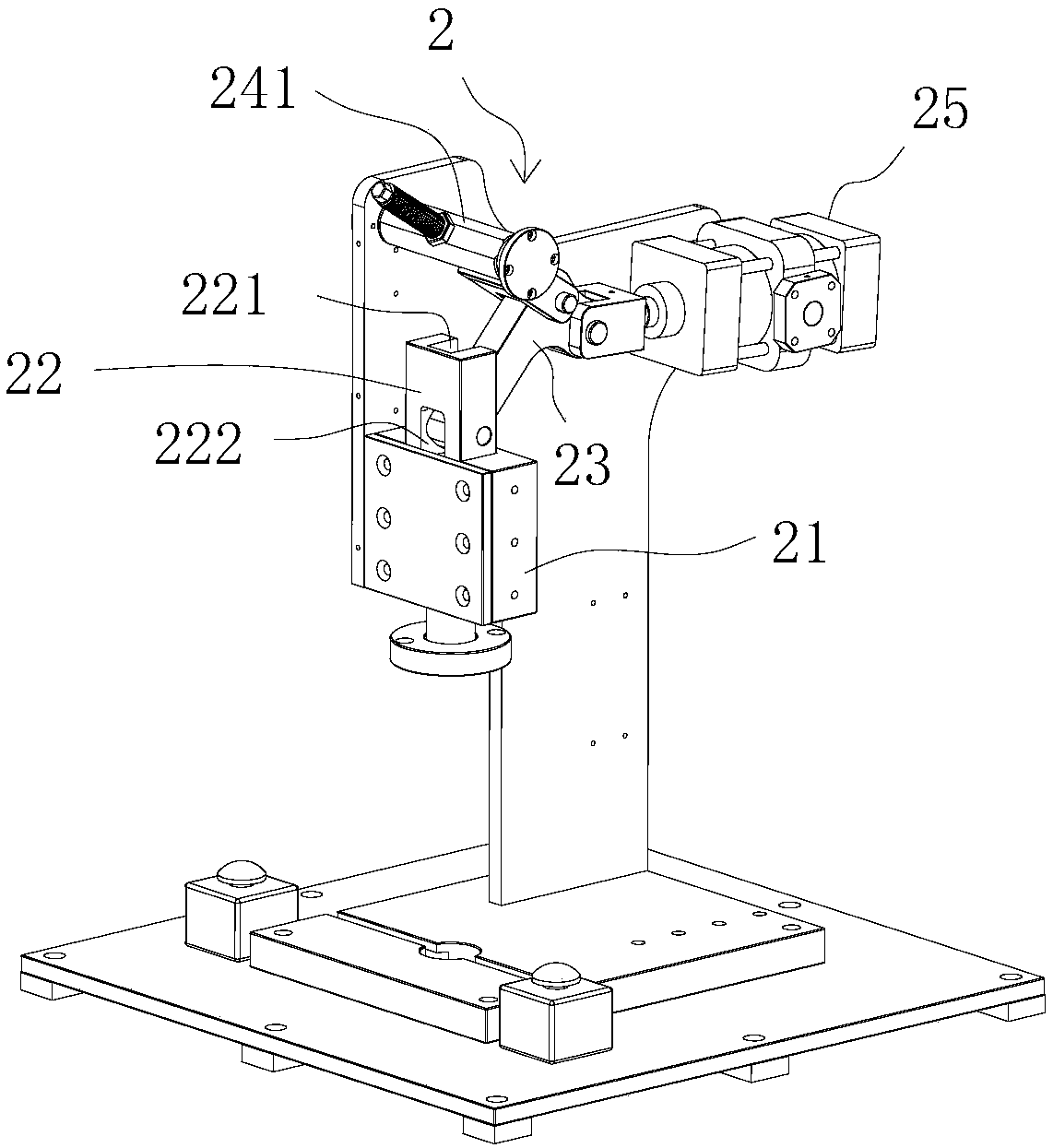
[0019] to combine figure 1 and figure 2 As shown, a pneumatic punch press in this embodiment includes a support frame 1 and a curved arm structure 2 matched with the support frame 1. Rail 21, the slide block 22 that slides with slide rail 21, the curved arm 23 that one end is hinged with the upper end of slide block 22, the stroke adjustment mechanism 24 that is hinged with the bend of curved arm 23, and the hinged arm 23 with curved arm 23 The other end of the cylinder 25 hinged, the lower end of the slide block 22 is provided with a handle 26. With this structural design, the cylinder pushes and pulls one end of the crank arm to drive the slider to slide up and down along the slide rail, thereby forming a large punching force.

[0020] Specifically, in this embodiment, the stroke adjustment me...


PUM


Abstract

The invention discloses a pneumatic punching machine. The pneumatic punching machine comprises support frames and a crank arm structure matched with the support frames. The crank arm structure comprises slide rails, a sliding block, a crank arm, a stroke adjusting mechanism and an air cylinder, wherein the slide rails are vertically arranged between the two adjacent sidewalls of the support frames; the sliding block is in sliding fit with the slide rails; one end of the crank arm is hinged to the upper end of the sliding block; the stroke adjusting mechanism is hinged to the bent part of the crank arm; the air cylinder is hinged to the other end of the crank arm; and the lower end of the sliding block is provided with a punch shank. Through the arrangement of the crank arm and push and pull of the air cylinder, punching force of the punch shank can be effectively increased; the stroke of the punching machine can be adjusted conveniently and rapidly through the stroke adjusting mechanism hinged to the bent part of the crank arm, so that the pneumatic punching machine meets the requirements of workpieces of different strokes. The pneumatic punching machine is large in punching force, high in punching efficiency and adjustable in punching stroke.

Description

technical field [0001] The invention relates to the technical field of machining equipment, in particular to a pneumatic punch. Background technique [0002] At present, most of the pneumatic punches used in the market are direct pressure punches or small electric punches; these punches have different advantages and disadvantages in the process of use. The direct pressure pneumatic punching machine is cheap, but the frame is rough, the precision is low, and the punching force is not enough; the small electric punching machine is fast enough, but the safety factor is low and the stroke height is limited. Contents of the invention [0003] The object of the present invention is to provide a pneumatic punching machine with high punching force, high punching efficiency and adjustable punching stroke. [0004] For reaching this purpose, the present invention adopts following technical scheme: [0005] A pneumatic punching machine, comprising a support frame, a curved arm stru...

Claims


Application Information

Patent Timeline
Patent Type & Authority Patents(China)
IPC IPC(8): B30B1/38B30B1/26B30B15/16
CPCB30B1/26B30B1/263B30B1/38B30B15/168
Inventor 吕奇华
Owner 艾佛森(深圳)科技有限公司
Features
  • R&D
  • Intellectual Property
  • Life Sciences
  • Materials
  • Tech Scout
  • Unparalleled Data Quality
  • Higher Quality Content
  • 60% Fewer Hallucinations
Learn More