
Air permeable material for data center cooling

a technology for data centers and air permeable materials, applied in the direction of electrical apparatus, electrical apparatus, electrical apparatus contruction details, etc., can solve the problems of large energy expenditure, unsatisfactory temperatures, and installation of relatively complex pressure sensing and monitoring systems, so as to prevent undue pressure buildup and inhibit excessive or under-pressurization conditions

Inactive Publication Date: 2010-07-29
IBM CORP
View PDF25 Cites 65 Cited by
  • Summary
  • Abstract
  • Description
  • Claims
  • Application Information

AI Technical Summary

Benefits of technology

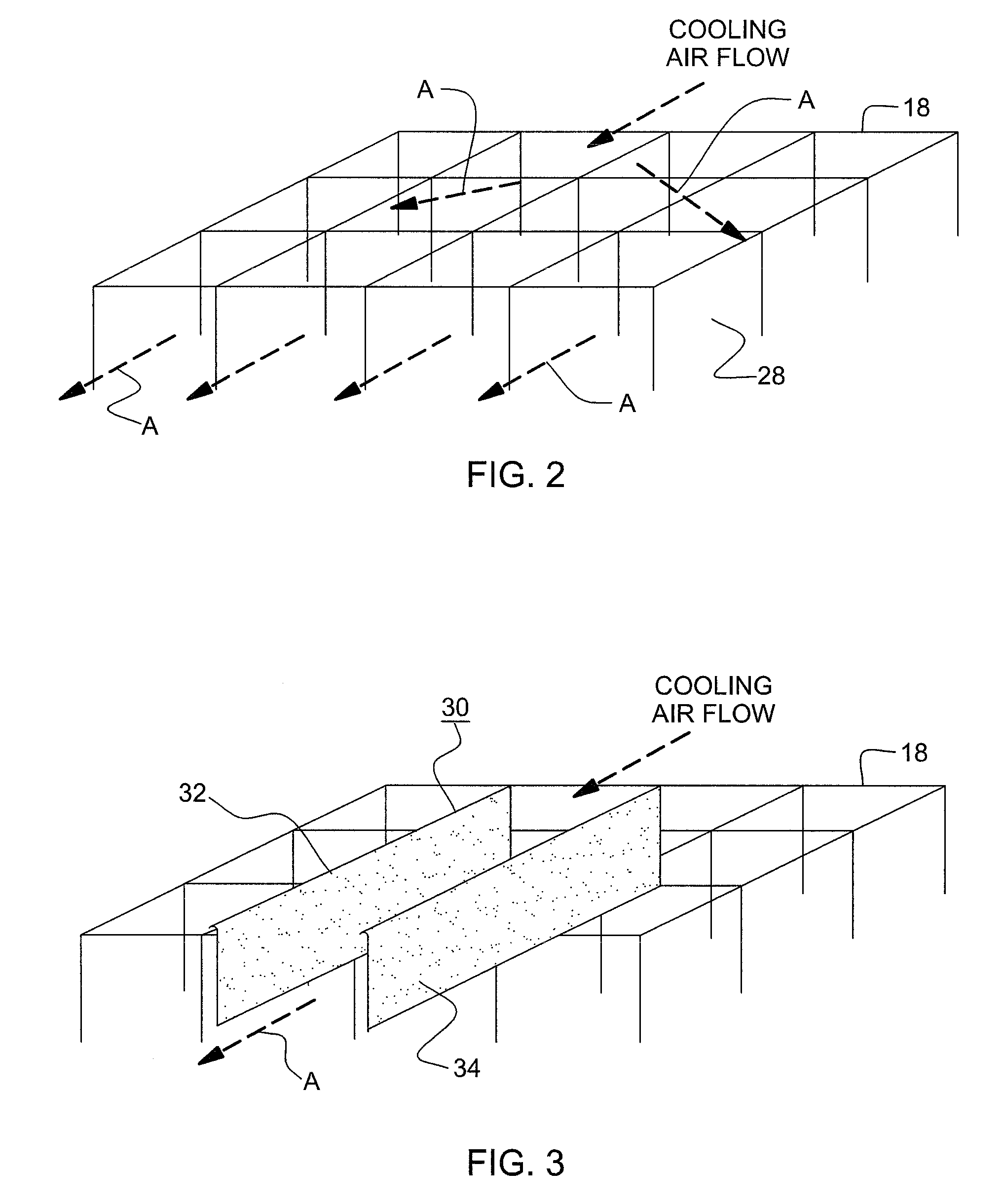
[0013]Accordingly, pursuant to a specific embodiment of the invention, there is provided ducting in the space beneath a raised floor of the aisles on which the electronic equipment is installed, whereby ducting comprises wall structure channeling the normally pressurized cooling air flow beneath the floor along desirable paths to provide for uniform distribution of cooling air into the various cold aisles between the computer equipment, while concurrently at least surface portions of the walls of the ducting is constituted of an air permeable material or including calibrated pores, which will enable a certain amount of the air flow to be diverted outwardly through the ducting, so as to thereby provide for a balancing in the amount of air flow being conveyed beneath the raised floor within the confines of the ducting. This permeable structure will, per se, prevent any undue pressure build up within the ducting caused by the flow of cooling air and inhibit any excessive or under-pressurized conditions to be encountered therein. As a result, this surface permeability will afford a controlled flow and pressurization of the cooling air beneath the raised floor without having to undergo the expenditures of complex, expensive and energy consuming sensing and control systems for the venting of any excessively-pressurized air, as may be encountered in the state-of-the-art.
[0014]Pursuant to a modified embodiment of the invention, there is provided a ducting structure for guiding the cooling air flow in a space beneath the raised floor, wherein rather than air-permeable wall surfaces, flap valves may be formed in the side walls of the ducting which, upon the pressure of the cooling air flowing within the ducting exceeding a specified limit, will deflect the flaps, preferably outwardly into open positions, thereby causing the venting of at least some of the air, thereby enabling the air flow to be expanded within the ducting and concurrently reducing any air pressure reigning therein to tenable levels.
[0015]Accordingly, it is an object of the present invention to provide conduits or ducting in a space beneath a raised floor supporting or mounting electronic or data equipment, which incorporates wall surfaces constituted of an air-permeable, or porous material having calibrated pores which will enable maintaining optimum air pressures in the ducting for the distribution of cooling air, preventing over-pressurization of air and any temperature rise caused by the resultant pressure increase encountered in the air flow.
[0016]Pursuant to a modified embodiment of the present invention, the conduits or ducting may comprise a plurality of outlet valves, such as simple flap valves or the like, which will effect a pressure relief from excessive air pressures so as to maintain an optimum pressure within the ducting for the distribution of cooling air, while preventing any heating of the air caused by an excessive pressure increase or over-pressurized air being conveyed therethrough.

Problems solved by technology

Although pipes, tubes or ducting has been employed in the space within the confines of the raised floor, in essence, beneath the level of the computer racks and equipment, in order to guide the cooling air flow within specified ducting or channels, the controlled directioning of the cooling air by means of either pipes, tubes or ducting causes the air flowing therethrough to be substantially compressed and, resultingly, heated to undesirable temperatures.
In dependence upon the ducting, tube or pipe sizes, the flow is congested and the air excessively pressurized, again raising the temperature of the cooling air, so as to render the air less efficient or even unusable in various locales of the data center beneath the computer equipment racks.
This concept enables the pressure in the cooling fluid to be controlled, however, it requires the installation of a relatively complex pressure sensing and monitoring system for controlling vents in order to maintain the pressures at viable levels.
Moreover, a system of that type also necessitates the expenditures of large amounts of energy or electrical power for the operation thereof.
Although these publications each generally, and in various instances, quite specifically describe the air cooling of high performance data centers containing computer equipment and servers contained in storage racks, by circulating cooling air beneath and then upwardly through the raised floors on which the equipment is supported, none of these references provide for a simple structure which will enable a controlled distribution of cooling air in the space beneath the raised floor supporting the electronic equipment, which will prevent any excess pressurization or heating of cooling air to undesirable temperatures, while concurrently affording a uniform distribution of cooling air to the various cold aisles that are present between racks of the computer equipment.

Method used


Image

  • Air permeable material for data center cooling
  • Air permeable material for data center cooling
  • Air permeable material for data center cooling

Examples


Embodiment Construction

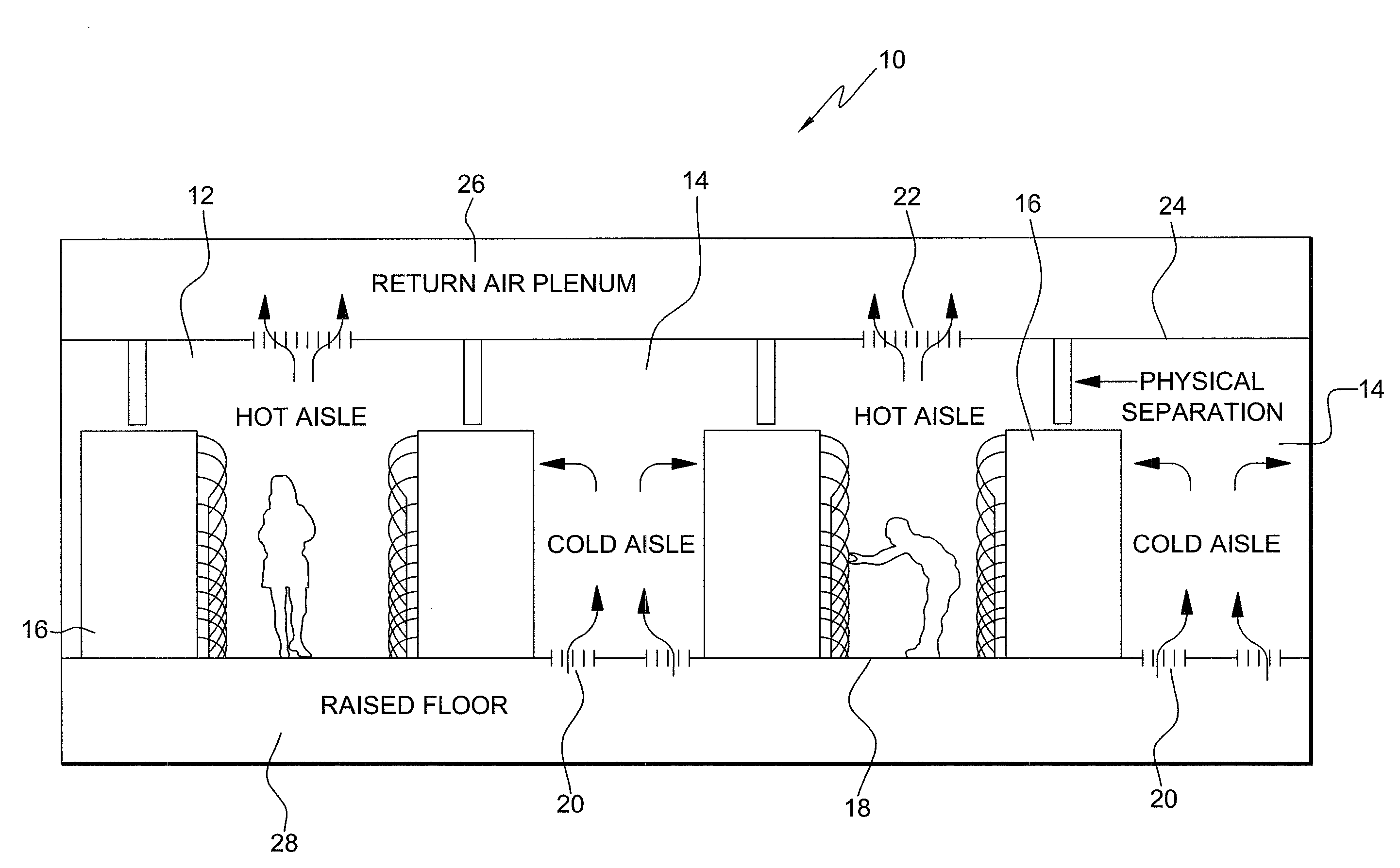
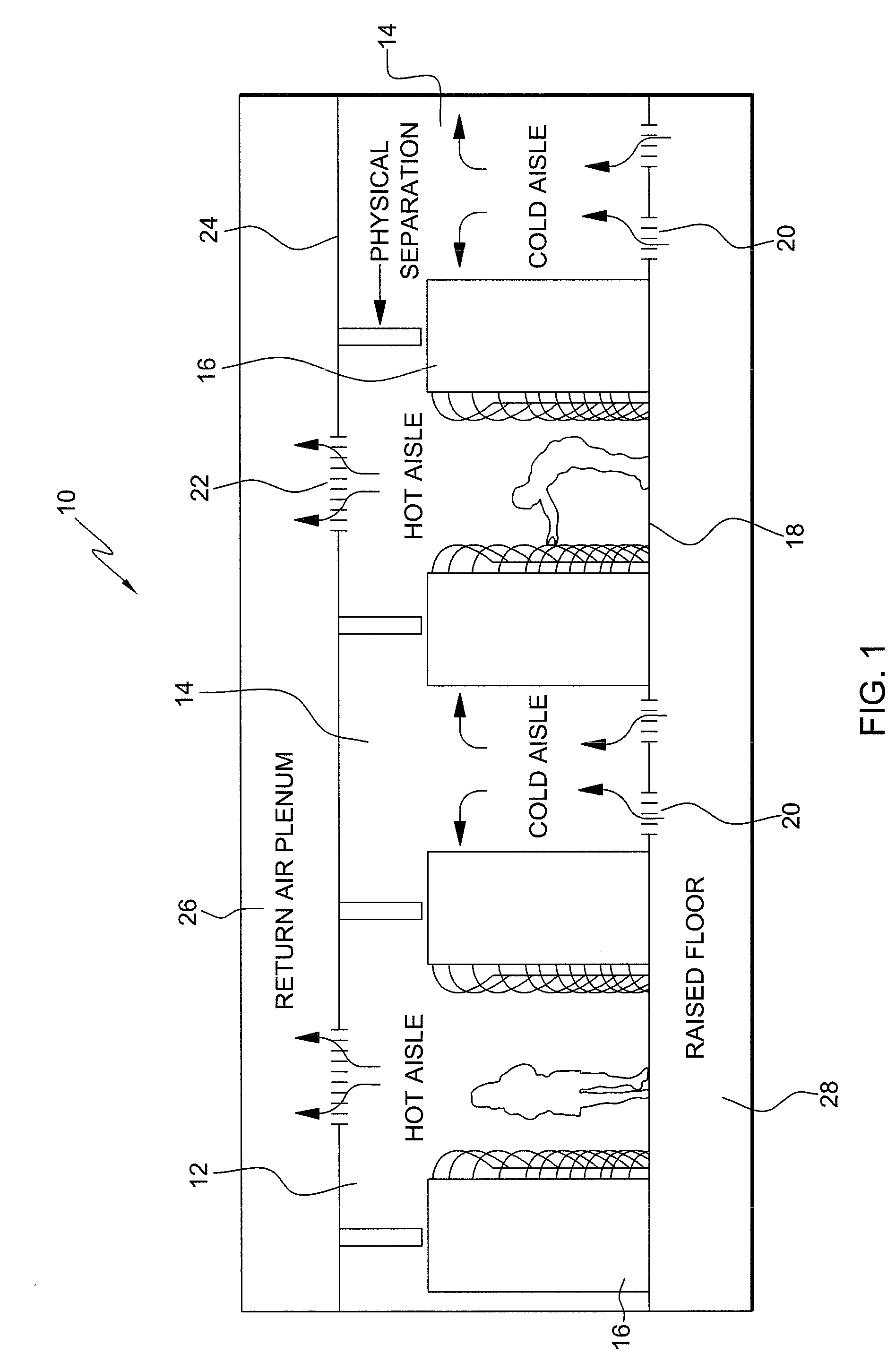
[0026]Referring to FIG. 1, there is illustrated diagrammatically, a high performance data center 10 with a hot aisle 12 and cold air aisle 14 arrangement for computer or electronic equipment racks 16, the latter of which are arranged and supported on a raised floor 18 which has flows of cooling air passing upwardly therethrough for cooling the equipment in the racks 16. In particular, the raised floor 18 has perforated tiles 20 which communicate with the cold aisles 14 between the racks 16 to enable cold air to rise upwardly and pass through the equipment into the hot aisles 12, which enables the hot air to rise upwardly through openings 22 in a ceiling 24 and into a return air plenum 26 for cooling and recycling the heated air.

[0027]In general, the structure of the raised floor 18, as illustrated in FIG. 1, is well-known in the technology and comprises part of the data center 10, wherein the equipment in the racks 16 is cooled through a forced air circulation. However, at various t...


PUM


Abstract

An arrangement for the controllable cooling of a data center, and more particularly, pertains to an arrangement for the provision of an improved computer room air-conditioning system (CRACS), which utilizes the installation of equipment above a raised floor and enables cooling air to be controllably dispensed through ducting installed below the computer installations. Also provided is a method for the controllable cooling of data center installations.

Description

BACKGROUND OF THE INVENTION[0001]1. Field of the Invention[0002]The present invention relates to an arrangement for the cooling of a data center, and more particularly, pertains to an arrangement for the provision of an improved computer room air-conditioning system (CRACS), which utilizes the installation of equipment above a raised floor and enables cooling air to be controllably dispensed from below the computer installations. Moreover, the invention also provides for a method for the controllable cooling of data center installations.[0003]The installation of air cooling systems for large-sized data centers, which house pluralities of computer devices, such as servers, in computer racks which are positioned on a raised floor and leave cold and hot aisles for flows of air between various racks containing the computer equipment, is well-known in the current technology. In particular, the raised floor provides for a space facilitating circulation of cooling air beneath the computer ...

Claims


Application Information

Patent Timeline
Patent Type & Authority Applications(United States)
IPC IPC(8): H05K5/00
CPCH05K7/20745
Inventor RODRIGUEZ, JEAN-MICHELFERRAND, ISABELLE
Owner IBM CORP
Learn More