Injection molding machine

Active Publication Date: 2008-06-26
FANUC LTD
View PDF4 Cites 4 Cited by
  • Summary
  • Abstract
  • Description
  • Claims
  • Application Information

AI Technical Summary

Benefits of technology

[0032]According to the present invention, since the closing point in time of the check ring can be detected more precisely, it is possible to easily and more precisely adjust the molding conditions such as the injection/hold pressure switching position and the switching position of the injec

Problems solved by technology

If the check ring 3 retracts and timing for closing the resin passage is varied, an amount of resin to be charged is also varied and the molding becomes unstable.
However, there is a problem that a pressure remains a groove 6 between flights 5 and the screw 1 behind the check ring mechanism immediately before injection, and the closing point in time is varied due to the remaining pressure.
Therefore, the injection capacity is varied between cycles due to the variation of the closing point in time and as a result, this affects quality of a molded article.
In this case, if a pressure sensor which comes into direct contact with resin is mounted, it is inevitable that a fine step is generated on inner surface of a cylinder, such an adverse influence that a carbide caused by remaining resin is mixed into a molded article can not be avoided.
Further, since a distortion of a cylinder is indirectly detected without direct contact with resin, the detection precision is deteriorated in the case of a pressure sensor which detects a resin pressure.
There are problems that any type of pressure sensor is expensive and its handling is troublesome, periodical maintenance and calibration are required.
According to the technique for detecting the closing point in time of t

Method used


Image

  • Injection molding machine
  • Injection molding machine
  • Injection molding machine

Examples


Example

[0083]A first embodiment of processing of the continuously molding cycle using the injection molding machine of the invention will be explained using a flowchart shown in FIG. 8.

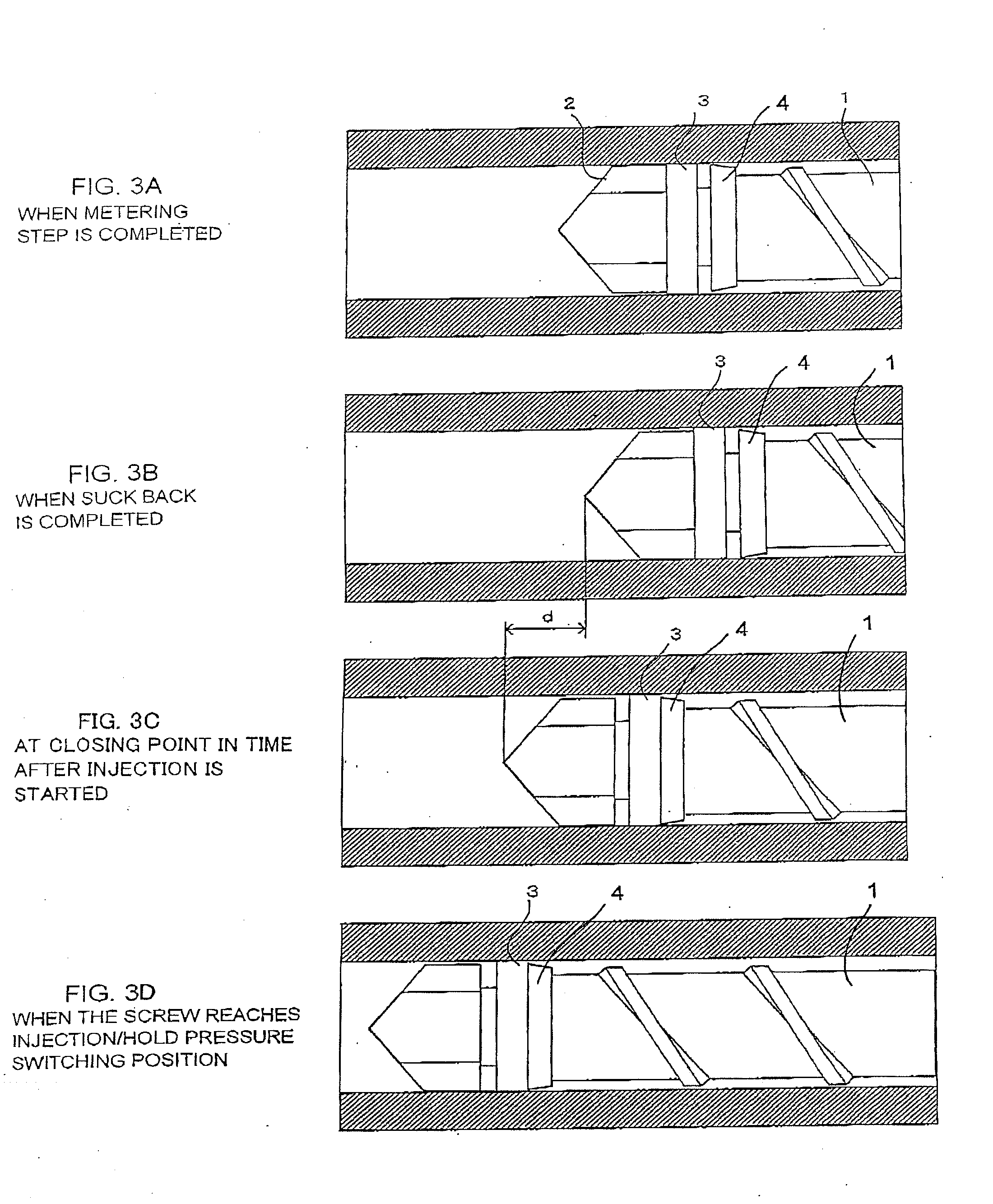
[0084]FIG. 8 is a flowchart showing an algorithm of processing for detecting a peak value of a screw rotational force when the screw moves forward in the injection / hold pressure step shown in FIG. 3A to FIG. 3D, for determining whether a molded article is non-defective or defective depending upon the detected peak value of the rotational force, screw position or time, and for correcting the molding condition such as the injection / hold pressure switching position and the injection speed switching position. In this embodiment, this processing is executed by the PMC CPU 21. In this embodiment, a correction amount of the injection / hold pressure switching position is obtained based on the screw position where the peak value of the rotational force is detected, and this injection / hold pressure switching position i...

Example

[0148]In the second embodiment of the processing of the continuously molding cycle explained using the flowchart in FIG. 10 in the pre-injection screw movement step, the peak value of the rotational force applied to the screw due to a reversely flowing resin is detected in the injection / hold pressure step, and a physical amount 1 at that time is obtained. Further, a peak value of the rotational force applied to the screw due to a reversely flowing resin is detected, and a physical amount 2 at that time is obtained. Then, based on the obtained physical amount 1 and physical amount 2, the VP switching position is corrected and non-defective / defective determination of the molded article is made. However, a peak value of a screw rotational force and a physical amount may be detected in the pre-injection screw movement step without carrying out detection of a rotational force peak value and a physical amount in an injection / hold pressure step, and the VP switching position may be correct...


PUM

PropertyMeasurementUnit
Forceaaaaaaaaaa
Pressureaaaaaaaaaa
Speedaaaaaaaaaa

Abstract

If a screw is moved forward after a metering step is completed, the screw moves in a state where a check ring on a tip end of the screw is in open state. Resin flows in a direction opposite to the injection direction. A rotational force is applied to the screw due to the backflow of the resin. If the check ring closes a resin passage, the rotational force acting on the screw is reduced. A peak time of the screw rotational force is detected as closing point in time of the check ring. Physical amounts such as a screw rotational force and a screw position at that timing are detected. Since the closing point in time of the check ring is precisely detected, correction of the injection/hold pressure switching position and the injection speed switching position can be adjusted more precisely. It is possible to precisely determine whether a molded article is non-defective or defective based on the detected physical amount.

Description

BACKGROUND OF THE INVENTION[0001]1. Field of the Invention[0002]The present invention relates to an injection molding machine having a screw provided with a check ring.[0003]2. Description of the Related Art[0004]There is conventionally used an injection molding machine having an injection mechanism whose screw provided at its tip end with a check ring mechanism so as to prevent backflow of resin at the time of injection like an in-line screw type injection molding machine. FIG. 1 shows one example of the check ring mechanism. The screw 1 is provided at its tip end with a screw head 2. A portion of the screw 1 which is reduced in diameter is provided between the screw head 2 and a main body of the screw 1. A check ring 3 is provided at the diameter-reduced portion such that the check ring 3 can move in an axial direction of the screw. A check seat 4 is provided at the diameter-reduced portion and on the side of the main body of the screw 1. The check seat 4 comes into intimate conta...

Claims


Application Information

Patent Timeline
IPC IPC(8): B29C45/76B29C45/77B29C45/80
CPCB29C45/52B29C45/768B29C2945/76381B29C2945/76187B29C2945/76013
Inventor TAKATSUGI, SATOSHIUCHIYAMA, TATSUHIROMARUYAMA, JUNPEI
Owner FANUC LTD
Why Eureka
Try Eureka