Process for Catalytic Cracking with Fine Control of the Residual Coke Content on the Catalyst after Regeneration

Inactive Publication Date: 2011-09-15
INST FR DU PETROLE
View PDF8 Cites 6 Cited by
  • Summary
  • Abstract
  • Description
  • Claims
  • Application Information

AI Technical Summary

Benefits of technology

[0102]The advantage of the invention resides in a regeneration system that makes possible a fine control of the residual coke content deposited on the regenerated catalyst, i.e., returning to the reaction zone, in an FCC that operates in partial combustion.
[0103]The configurations of the regeneration zone that are described in FIGS. 1 to 3 are actually particularly suited to an adjustment of the control of the activity of the catalyst via the deposition of coke on the catalyst. The action means is the flow of catalyst that has undergone total regeneration in the second regeneration stage (8) to the first regeneration stage (2), or to the fluidized mixing chamber (23).
[0104]Actually, the quantity of catalyst that is exposed to total regeneration conditions depends directly on the circulation of catalyst that circulates from the first regeneration stage (2) to the second stage (8). This quantity of catalyst is easily controllable through transport systems that are equipped with valves (21) that are located between the two regenerators. It is possible, for example, to impose a flow set point by controlling the opening of the valve that is positioned on the transport line between the regenerator that operates by partial c

Problems solved by technology

There is not enough oxygen present in the regeneration air to implement the total combustion of the carbon and the hydrogen that are present in the coke.
For the same quantity of burned coke, it therefore results in a more significant reheating of the catalyst.
The partial combustion is less exothermic and leads to a more limited reheating of the catalyst.
In contrast, it does not make

Method used


Image

  • Process for Catalytic Cracking with Fine Control of the Residual Coke Content on the Catalyst after Regeneration
  • Process for Catalytic Cracking with Fine Control of the Residual Coke Content on the Catalyst after Regeneration
  • Process for Catalytic Cracking with Fine Control of the Residual Coke Content on the Catalyst after Regeneration

Examples


examples

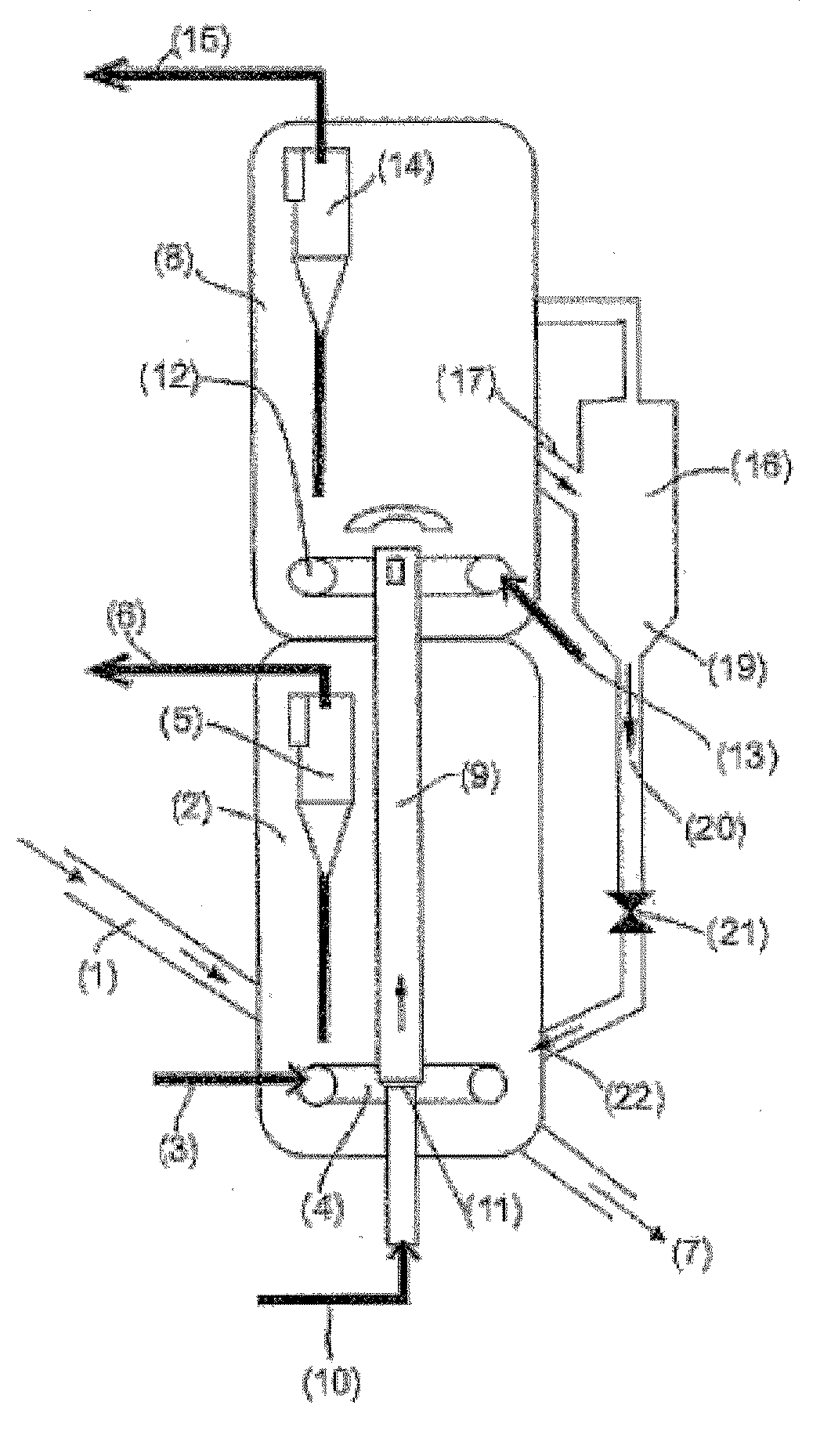
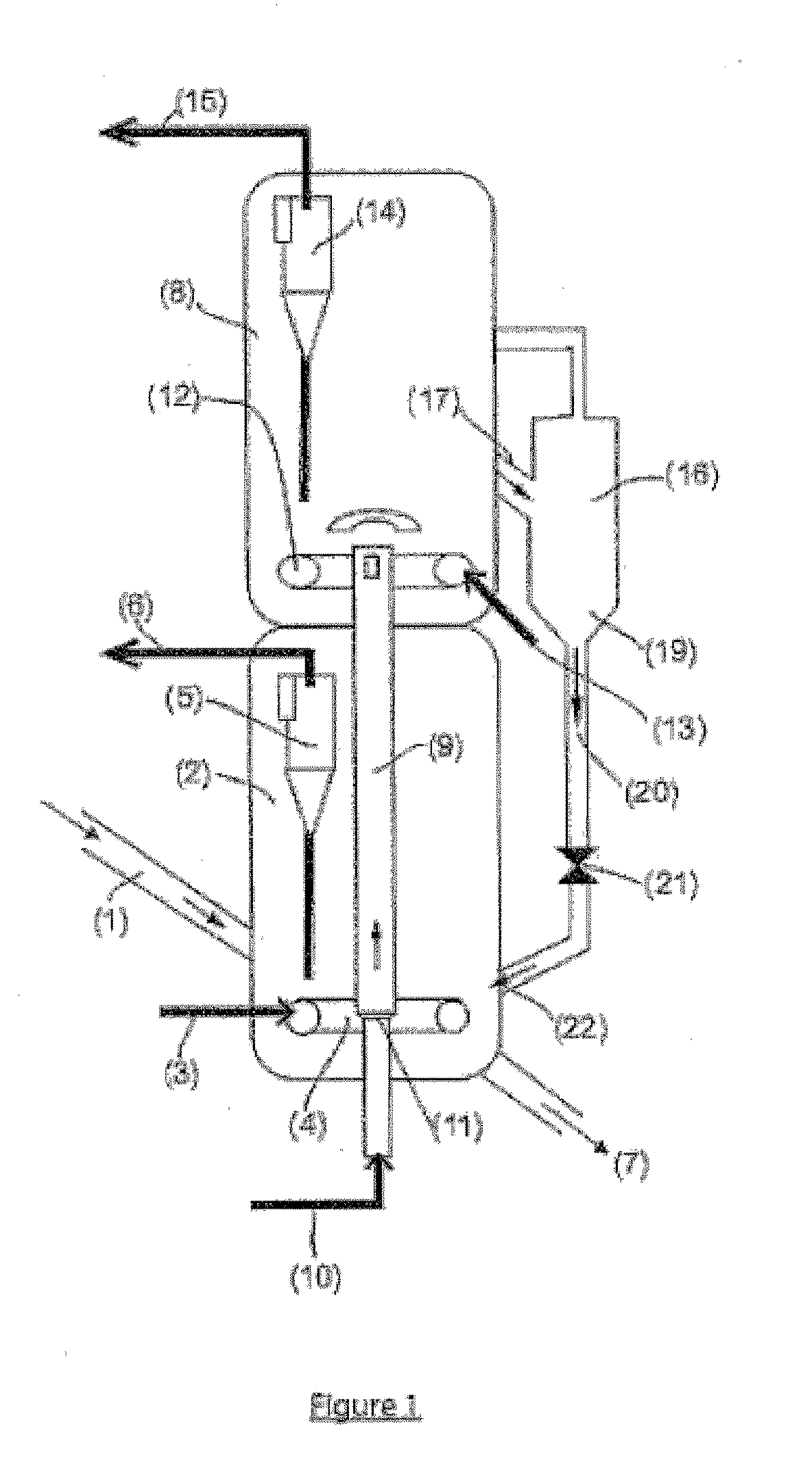
[0116]The first example describes the operation of a catalytic cracking unit that operates with a regeneration system that is identical to the one that is described in FIG. 1.

[0117]The feedstock flow rate (Ff) in the reaction zone and the cracking conditions (ROT=output temperature of the riser) are kept constant at a very moderate temperature of 490° C. that promotes the production of LCO.

[0118]The catalyst is regenerated in a system with two regenerators, only a portion of the catalyst being exposed to total combustion conditions.

[0119]Table 1 below shows that by varying the quantity of catalyst between the two regenerators, and by adjusting the streams of air in the first and the second regenerator for keeping constant total combustion conditions (1% by volume of excess dry smoke) in the second regenerator and partial combustion conditions (CO / CO2 molar equal to 1) in the first regenerator, it is possible to vary the coke content of the regenerated catalyst (CRCreg) in a field th...


PUM

PropertyMeasurementUnit
Temperatureaaaaaaaaaa
Fractionaaaaaaaaaa
Fractionaaaaaaaaaa

Abstract

This invention describes a two-stage regeneration zone that has a regenerated catalyst circuit such as the one that results from the mixing of a partially regenerated catalyst with a residual coke rate of between 0.3 and 0.7% and a totally regenerated catalyst with a coke rate that is less than 0.15%. All things being equal, this double-population regenerated catalyst enables the maximization of the LCO yield.

Description

FIELD OF THE INVENTION[0001]This invention relates to the field of the catalytic cracking of petroleum fractions, more particularly the so-called “heavy” fractions, i.e., fractions of which less than 10% by weight of hydrocarbon have a boiling point that is less than 350° C.[0002]The invention relates more particularly to a catalytic cracking process that consists of at least one reaction zone that brings the catalyst and the hydrocarbons into contact for implementing the catalytic cracking reactions, and a zone for regeneration of the catalyst that consists of at least two interconnected fluidized beds and that enables the fine control of the residual coke content on the catalyst with contents that are greater than 0.15% by weight, preferably greater than 0.25% by weight. The particular arrangement of the regeneration zone that is the object of this invention makes it possible to limit the activity of the catalyst in the reaction zone, whereby the process is characterized by the fa...

Claims


Application Information

Patent Timeline
IPC IPC(8): C10G11/00
CPCC10G11/182C10G2300/708C10G2300/301C10G11/187Y02P30/40
Inventor ROUX, ROMAINGAUTHIER, THIERRY
Owner INST FR DU PETROLE
Why Eureka
Try Eureka