A push wheel type gluing device

A push-wheel and wheel-type technology, applied in the field of push-wheel gluing devices, can solve the problems affecting processing progress and efficiency, material stacking and collapse, etc., and achieve the effect of improving processing progress and efficiency.

Active Publication Date: 2018-05-18
重庆新锐科技服务有限公司
View PDF7 Cites 2 Cited by
  • Summary
  • Abstract
  • Description
  • Claims
  • Application Information

AI Technical Summary

Problems solved by technology

[0003] The present invention intends to provide a push-wheel type gluing device to solve the problem that the existing gluing profiles are flattened by heavy objects due to stacking and collapsing of materials, which affects the processing progress and efficiency

Method used


Image

  • A push wheel type gluing device
  • A push wheel type gluing device
  • A push wheel type gluing device

Examples


Embodiment Construction

[0014] The present invention will be described in further detail below by means of specific embodiments:

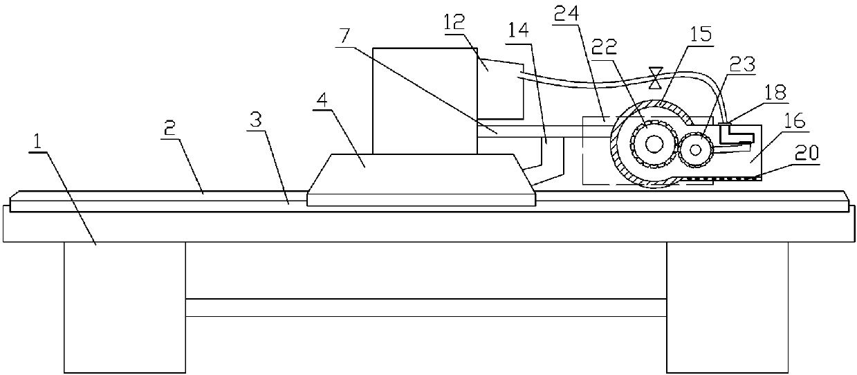
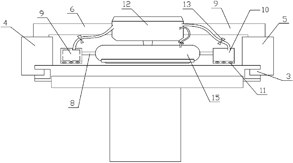
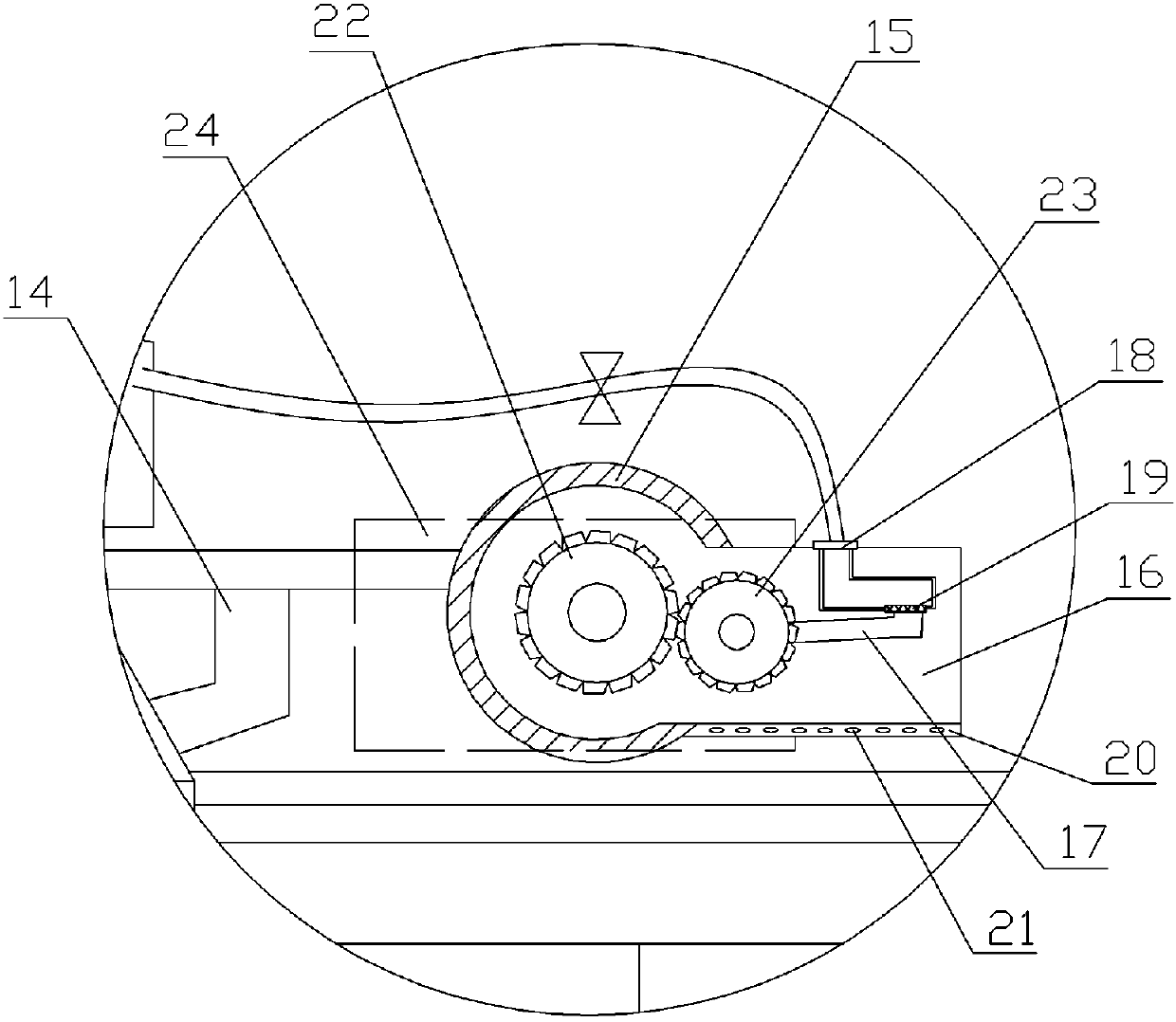
[0015] The reference signs in the drawings of the specification include: machine base 1, workbench 2, guide rail chute 3, first slider 4, second slider 5, beam 6, tie rod 7, connecting rod 8, cavity 9, pressure Block 10, liquid outlet hole 11, feeding box 12, liquid stop valve 13, support frame 14, rolling roller 15, glue chamber 16, rotating shaft 17, feed port 18, sealing plug 19, lower rubber plate 20, drop Hole 21, first gear 22, second gear 23, protective cover 24.

[0016] The embodiment is basically as attached figure 1 , figure 2 Shown: a push wheel type gluing device, including a machine base 1 and a workbench 2 arranged on the machine base 1, the workbench 2 is in the shape of a rectangular plate, and the front and rear sides of the workbench 2 along the length direction are both A guide rail chute 3 is provided, and the guide rail chute 3 on the front and r...


PUM


Abstract

The invention discloses a push-wheel gluing device which comprises an engine base and a workbench arranged on the engine base, wherein the workbench takes the shape of a rectangular plate; guide rail sliding grooves are arranged on both the front and rear sides of the workbench in the length direction; a first sliding block and a second sliding block are respectively in sliding fit with the guide rail sliding grooves on the front and rear sides, driven by a motor, and connected through a cross beam; a pull rod is arranged on the cross beam; a supporting frame is mounted on the pull rod; a rolling drum is hinged onto the supporting frame; a glue accommodating cavity is formed in one side end of the rolling drum; a sealing plug capable of sealing a feeding port is fixedly connected onto a rotating shaft; a plurality of horizontally-arranged drip holes are formed in a glue discharging plate; the feeding port communicates with a feeding box through a rubber tube; a first gear is fixedly connected with one end part of the rolling drum; and a second gear meshed with the first gear is mounted at one end part of the rotating shaft. According to the push-wheel gluing device disclosed by the invention, the problems that in the prior art, glued profiles need to be stacked and pressed by a weight, the stacked profiles are liable to collapse, and then the machining progress and efficiency are influenced can be solved.

Description

technical field [0001] The invention relates to the technical field of product packaging equipment, in particular to a push-wheel type gluing device. Background technique [0002] Product packaging profiles are used to form packaging bags or other packaging containers, etc., to facilitate the storage of items. Many large-scale equipment will be used in machinery processing plants, and large packaging materials will be used by manufacturers of production equipment. The length and width values ​​are different. Larger, such as outer cartons, etc., after the profile packaging factory has produced the semi-finished product of the outer packaging of the product (that is, a flat packaging profile), it needs to glue the packaging material, and then fold the glued packaging material Or processed into a specific shape to form a box or container. In this process, the profile or packaging material after gluing needs to be flattened. Because of gluing or other reasons, it is necessary to...

Claims


Application Information

Patent Timeline
Patent Type & Authority Patents(China)
IPC IPC(8): B31B50/62B31B70/62
Inventor 张涛
Owner 重庆新锐科技服务有限公司
Why Eureka
Try Eureka