

Micropore detection instrument
A detector and micro-hole technology, applied in the field of micro-hole detectors, can solve the problem of inability to determine the penetration state of each micro-hole on the workpiece
- Summary
- Abstract
- Description
- Claims
- Application Information
AI Technical Summary
Problems solved by technology
Method used
Image

Examples
Embodiment Construction
[0021] The present invention will be described in further detail below in conjunction with accompanying drawing embodiment:
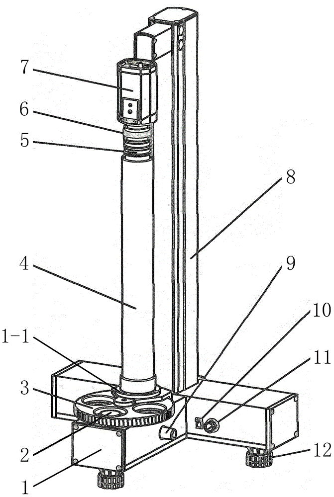
[0022] figure 1 The shown micropore detector mainly includes a base 1 , an object stage, a light-shielding tube 4 , a camera 7 , a frame 8 , a light source and a cooling device. The base 1 of this embodiment is a T-shaped shell, and three adjustment feet 12 are installed on the bottom of the base 1, and a frame 8 and a detection station frame 1-1 are fixed on the top of the base 1, and the detection station frame 1-1 1 and the base 1 is installed with a stage, the stage of this embodiment is a rotating stage 3 hinged between the detection station frame 1-1 and the base 1, the rotating stage 3 is provided with four A workpiece placement hole for placing the detected workpiece 2. The camera 7 is installed on the upper part of the erected frame 8, the lens of the camera 7 is connected with the light-shielding tube 4 between the detection station frame 1-...
PUM
 Abstract
Description
Claims
Application Information