
Micropore detection method based on luminous flux

A detection method and luminous flux technology, applied in the field of optical detection, can solve the problem of inability to determine the permeability state of micropores

Inactive Publication Date: 2016-10-12
WUZHOU OKA OPTICAL INSTR
View PDF7 Cites 1 Cited by
  • Summary
  • Abstract
  • Description
  • Claims
  • Application Information

AI Technical Summary

Problems solved by technology

[0003] The purpose of the present invention is to provide a microhole detection method based on luminous flux, which can solve the problem that the existing microhole detection cannot determine the permeability state of each microhole on the workpiece in one imaging

Method used


Image

  • Micropore detection method based on luminous flux

Examples


Embodiment Construction

[0016] The present invention will be described in further detail below in conjunction with accompanying drawing embodiment:

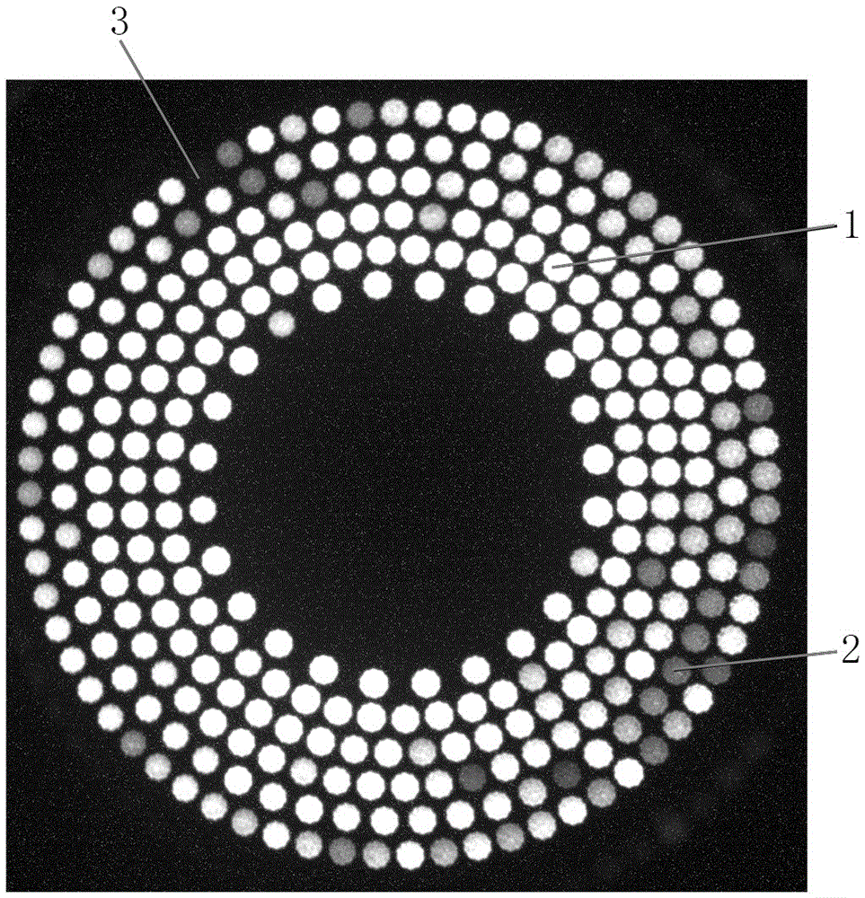
[0017] The detection object of this embodiment is a circular microhole workpiece with a diameter of 42.5 mm. Through the following microhole detection method based on luminous flux, all the microholes distributed in the φ42.5 mm circle are completely imaged at one time, and the diameter of each microhole is detected. transparent state. The CCD target surface size of the camera used in this embodiment is 1 / 2", the imaging magnification β=0.09× of the optical imaging system, and the minimum sensing illuminance of the camera is 0.001Lux; the optical imaging lens adopts a telecentric flat field lens , the focal length of the flat-field lens is 40.5mm, the working distance is 495mm, the numerical aperture is 0.025, and the edge distortion value is less than 0.014%; the optical path between the workpiece to be detected and the imaging lens of the camera is is...


PUM


Abstract

The invention discloses a microhole detection method based on luminous flux, and relates to the technical field of optical detection methods. The method includes placing a workpiece to be detected in an imaging optical path, and a camera collects an image of the microhole of the workpiece to be detected by an optical imaging system. The image processing system outputs the image to the display screen after processing, and observes the image to determine the transparent state of the micropores. Among them, the optical imaging system adopts the working mode of image square defocus to reduce the imaging, and completes all the micropores on the workpiece at one time. The image is imaged on the image receiving target surface of the camera. The microhole image received by the camera is amplified and output to the display screen to form diffuse spots. These diffuse spots show corresponding gray values ​​through the luminous flux of the microholes of the workpiece to be detected. The transparent state of each micropore on the workpiece to be detected is judged by observing the brightness and darkness of the diffuse light spot. The invention solves the problem that the existing microhole detection cannot determine the transparent state of each microhole on the workpiece in one imaging.

Description

technical field [0001] The invention relates to the technical field of optical detection methods, in particular to a microhole detection method based on light flux. Background technique [0002] There are many tiny through-holes on microporous workpieces such as microporous filter membranes. The pore throughput of these microporous workpieces has a great impact on their performance. In order to ensure the quality of the workpiece, it is necessary to use optical instruments to detect the penetration of the micropores on the workpiece. The situation, that is, to detect which of the numerous micro-holes on the workpiece are full-through holes, which are half-through holes and which are unreasonable. The diameter of the micropores on the microporous workpiece is mostly about 8 μm. The hole with a diameter of 8 μm is a full-through hole, and the hole with a diameter much smaller than 8 μm is a half-through hole or a non-through hole. Therefore, the existing micropore detection me...

Claims


Application Information

Patent Timeline
IPC IPC(8): G01D21/00
CPCG01D21/00
Inventor 张景华
Owner WUZHOU OKA OPTICAL INSTR
Learn More