
Laser direct writing energy correction method and device

A technology of laser direct writing and energy, which is applied in the direction of exposure devices, optics, and optomechanical equipment in the photolithography process. It can solve the problems of not being able to obtain the reflected beam of the micromirror, and achieve the effect of solving the problem of brightness uniformity and improving accuracy.

Active Publication Date: 2021-01-29
GIS TECH INC
View PDF4 Cites 0 Cited by
  • Summary
  • Abstract
  • Description
  • Claims
  • Application Information

AI Technical Summary

Problems solved by technology

[0006] The embodiment of the present invention provides a laser direct writing energy correction method and device, which avoids the problem that the detector cannot obtain all the reflected beams of the micromirrors of the micromirror array, realizes the complete imaging of the micromirror array by the detector, and improves the laser direct writing performance. Accuracy of energy correction to resolve brightness uniformity issues

Method used


Image

  • Laser direct writing energy correction method and device
  • Laser direct writing energy correction method and device
  • Laser direct writing energy correction method and device

Examples


Embodiment Construction

[0053] The present invention will be further described in detail below in conjunction with the accompanying drawings and embodiments. It should be understood that the specific embodiments described here are only used to explain the present invention, but not to limit the present invention. In addition, it should be noted that, for the convenience of description, only some structures related to the present invention are shown in the drawings but not all structures.

[0054]Laser direct writing uses a laser beam with variable intensity to perform variable dose exposure on the resist material on the surface of the substrate. After development, the required relief profile is formed on the surface of the resist layer. The laser direct writing imaging device can reflect the imaging through the micromirror array (that is, the digital micromirror device, also known as DMD). The modulated light beam is projected onto the photosensitive substrate to achieve the purpose of photolithogra...


PUM


Abstract

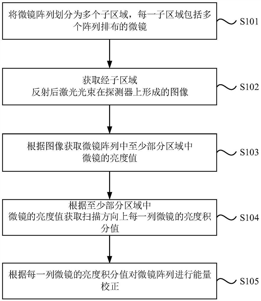
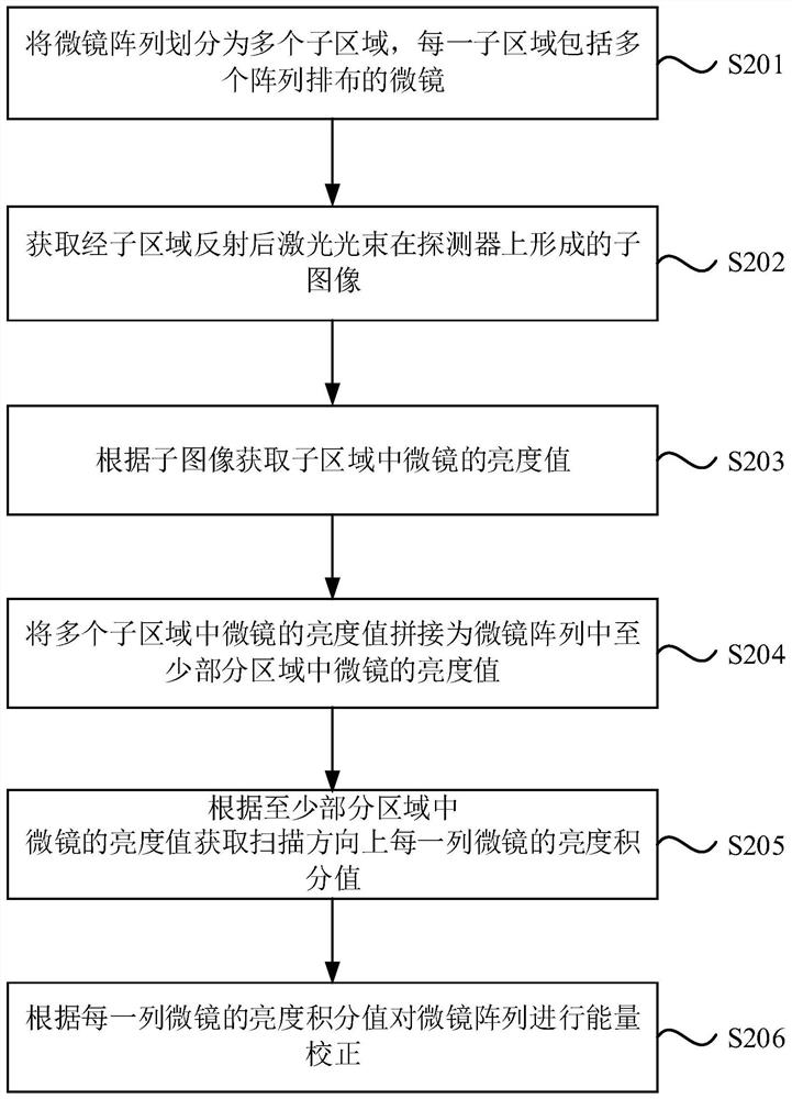
The embodiment of the invention provides a laser direct writing energy correction method and device. The method comprises the steps: enabling a micro-mirror array to be divided into a plurality of sub-regions, and enabling each sub-region to comprise a plurality of micro-mirrors which are arranged in an array mode; acquiring an image formed by a laser beam reflected by the sub-region on a detector; acquiring brightness values of micro-mirrors in at least a part of the region in the micro-mirror array according to the image; obtaining a brightness integral value of each column of micro-mirrorsin a scanning direction according to the brightness values of the micro-mirrors in the at least partial region; and performing energy correction on the micro-mirror array according to the brightness integral value of each column of the micro-mirrors. The embodiment of the invention provides the laser direct writing energy correction method and device which solve a problem that the detector cannotacquire all micro-mirror reflection beams of the micro-mirror array, realize complete imaging of the detector on the micro-mirror array, and improve the accuracy of laser direct writing energy correction so that the problem of brightness uniformity is solved.

Description

technical field [0001] The invention relates to laser direct writing technology, in particular to a laser direct writing energy correction method and device. Background technique [0002] Laser direct writing imaging equipment, also known as direct image transfer equipment, is an important equipment in the field of semiconductor and printed circuit board (PCB) production that is different from traditional semi-automatic exposure equipment. The pattern generator is used to replace the mask plate of traditional imaging equipment, so that the graphic data of the computer can be directly exposed to the wafer or PCB board, which saves the time of board making and the cost of making the mask plate, and can be used as the mask plate itself. And the equipment of most manufacturers in the past uses the spatial light modulator (SLM) as the pattern generator. SLM includes digital micromirror device (DMD) and liquid crystal display (LCD). SLM includes an independently addressable and co...

Claims


Application Information

Patent Timeline
IPC IPC(8): G03F7/20
CPCG03F7/70558G03F7/704G03F7/2053
Inventor 陈国军吴景舟马迪
Owner GIS TECH INC
Learn More