DR image splicing method

A video and image technology, applied in the field of image processing, can solve problems such as increased exposure times, artifacts, and patient hazards, and achieve the effects of simple shooting scenes, elimination of ghosting, and good tolerance

Active Publication Date: 2016-10-12
NANJING PERLOVE RADIAL VIDEO EQUIP
View PDF6 Cites 3 Cited by
  • Summary
  • Abstract
  • Description
  • Claims
  • Application Information

AI Technical Summary

Problems solved by technology

However, the current clinical DR system can only provide a limited field of view, which is limited in many situations, for example: in orthopedic diagnosis and surgical treatment of the human spine or long bones, it is crucial to obtain a complete anatomical structure image, when When doctors need to observe the edge area of ​​an image, they need to manually stitch multiple images of different parts with overlapping areas at different times or use third-party tools such as photoshop according to their own medical experience.
Although researchers have explored various image stitching algorithms, they are mostly used for stitching camera photos.
Camera photos are very different from the imaging principle of the DR system, thus causing difficulties in X-ray image registration
The current stitching algorithms are all transplanted from camera stitching, without considering the perspective effect of X-rays
Moreover, the existing image stitching methods have high requirements on the degree of overlap, and a higher degree of overlap means an increase in the number of exposures, which is extremely harmful to patients.
Moreover, the overlapping requirements are fixed, and images with different overlapping degrees cannot be flexibly processed.
At the same time, the existing X-ray stitching algorithm handles rotation and zooming, which increases the complexity of the algorithm and increases the running time of the algorithm exponentially. However, such complex shooting scenes do not exist in actual DR shooting, and 99% of them use upright photography.
There are still obvious artifacts in the existing splicing and fusion algorithms

Method used


Image

  • DR image splicing method
  • DR image splicing method
  • DR image splicing method

Examples


Embodiment Construction

[0029] Such as Figure 1-Figure 5 As shown, the present invention discloses a method for splicing DR images, and the method comprises the following steps:

[0030] 1) Collect images: DR system collects images by means of upright photography;

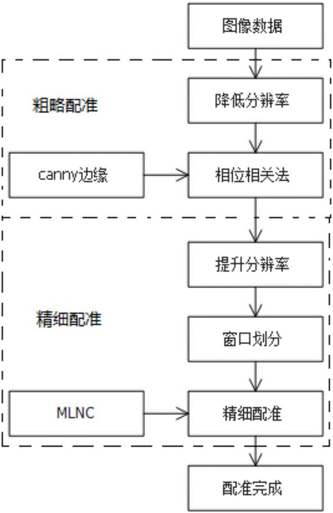
[0031] 2) Image registration: First, the image data collected by the DR system is roughly registered at low resolution, and then the roughly registered image data is finely registered at high resolution;

[0032] 3) Image fusion: the image processed in step 2) is fused using a multi-band-based curve to eliminate ghosting in the image.

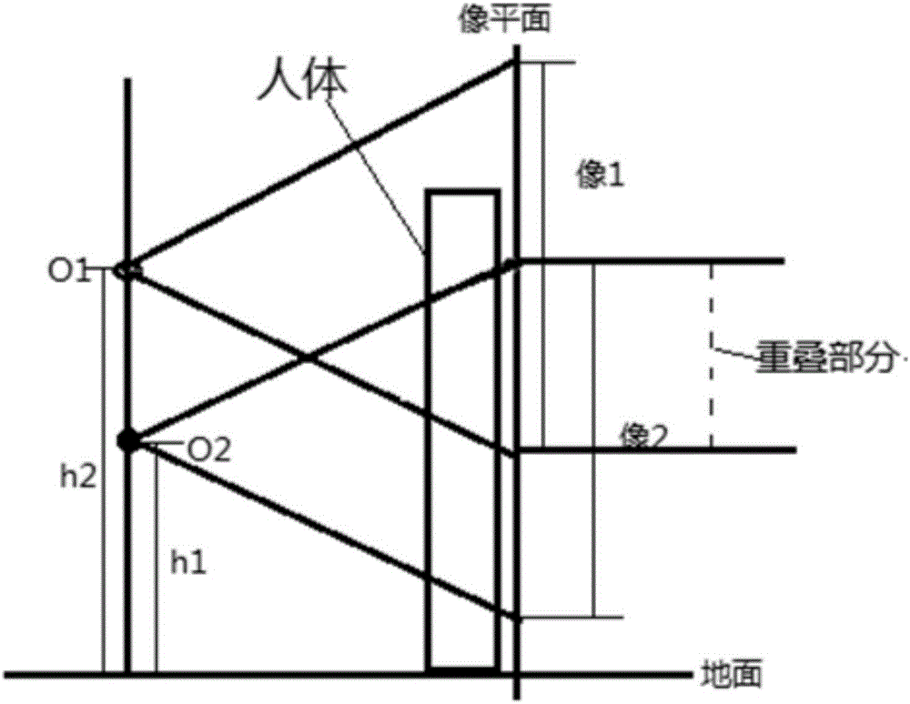
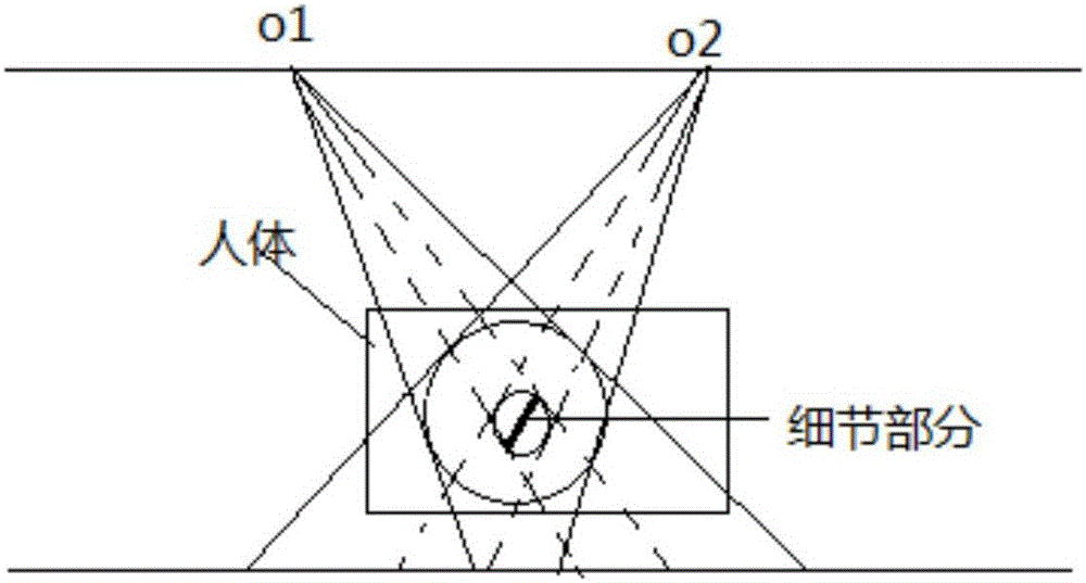
[0033] Such as figure 1 As shown, when the image is collected in step 1), the main optical axis of the ray of the DR system is perpendicular to the image plane, and the baseline during shooting is parallel to the image plane.

[0034] The DR system is used to repeatedly shoot the image, and the overlapping part of the image imaging is greater than one tenth of the distance from the ray source during th...


PUM


Abstract

The invention relates to the technical field of image processing, and especially relates to a DR image splicing method. The method comprises the steps: image collection: enabling a DR system to collect the image in a mode of normal case photography; image registering: firstly carrying the rough registering of the image data, collected by the DR system, at low resolution, and secondly carrying out the fine registering of the image data at high resolution after rough registering; image fusion: employing a curve based on multiple bands for fusion, and eliminating the ghost in the image. The method employs the DR system for normal case photograph, is simple in photographing scene, and is better in tolerance for the X-ray perspective effect of the DR system through the rough and fine registering. The image fusion technology aims at a problem that a conventional splicing method has a ghost, and the method provided by the invention effectively avoids the ghost through employing the curve fusion based on multiple bands, i.e., eliminating the ghost.

Description

technical field [0001] The present invention relates to the technical field of image processing, in particular to a method for splicing DR images. Background technique [0002] With the continuous development of medical technology, direct digital X-ray photography system (Digital Radiography or DR system) has been widely used in diagnosis and medicine. However, the current clinical DR system can only provide a limited field of view, which is limited in many situations, for example: in orthopedic diagnosis and surgical treatment of the human spine or long bones, it is crucial to obtain a complete anatomical structure image, when When a doctor needs to observe the edge area of ​​an image, he must manually stitch multiple images of different parts with overlapping areas at different times or use third-party tools such as photoshop according to his own experience in seeing a doctor. Although researchers have explored various image stitching algorithms, they are mostly used for ...

Claims


Application Information

Patent Timeline
Patent Type & Authority Applications(China)
IPC IPC(8): G06T3/40G06T7/00
CPCG06T3/4038
Inventor 刘金虎王东辉加冯刚
Owner NANJING PERLOVE RADIAL VIDEO EQUIP
Why Eureka
Try Eureka