Low Profile Radial Wire Helical Antenna

A helical antenna and radial line technology, applied in the microwave field, can solve the problems of large volume and complicated processing of helical antennas, and achieve the effects of low profile, reduced phase requirements, and reduced distance requirements

Active Publication Date: 2018-10-23
浙江恩碧技创新科技有限公司
View PDF2 Cites 0 Cited by
  • Summary
  • Abstract
  • Description
  • Claims
  • Application Information

AI Technical Summary

Problems solved by technology

[0005] The embodiment of the present invention provides a low-profile radial wire helical antenna; to solve the technical problem of complex and large-volume helical antenna processing in the prior art

Method used


Image

  • Low Profile Radial Wire Helical Antenna
  • Low Profile Radial Wire Helical Antenna
  • Low Profile Radial Wire Helical Antenna

Examples


Embodiment Construction

[0019] In order to facilitate the understanding of the present invention, the present invention will be described more fully below with reference to the associated drawings. A preferred embodiment of the invention is shown in the drawings. However, the present invention can be embodied in many different forms and is not limited to the embodiments described herein. Rather, these embodiments are provided so that the disclosure of the present invention will be thorough and complete.

[0020] It should be noted that when an element is referred to as being “fixed” to another element, it can be directly on the other element or there can also be an intervening element. When an element is referred to as being "connected to" another element, it can be directly connected to the other element or intervening elements may also be present. The terms "vertical," "horizontal," "left," "right," and similar expressions are used herein for purposes of illustration only.

[0021] Unless otherw...


PUM


Abstract

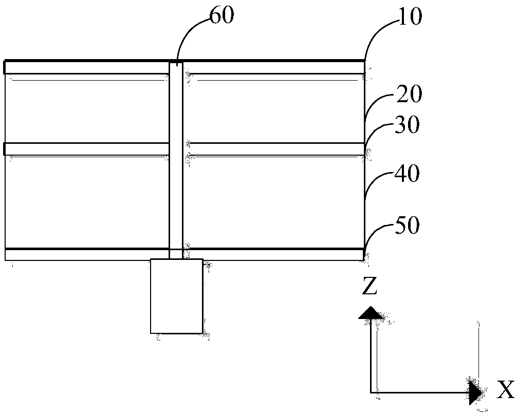
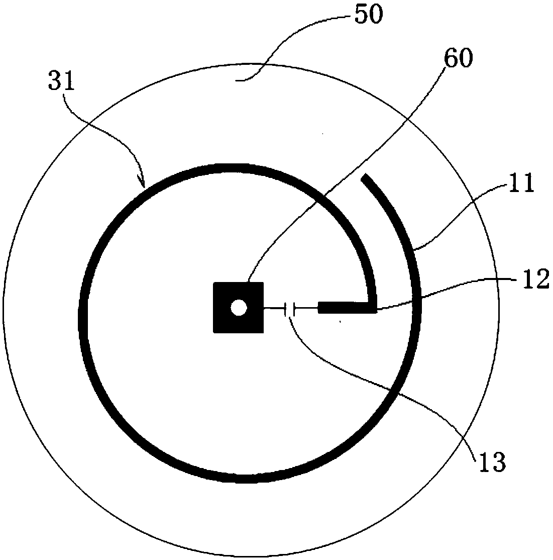
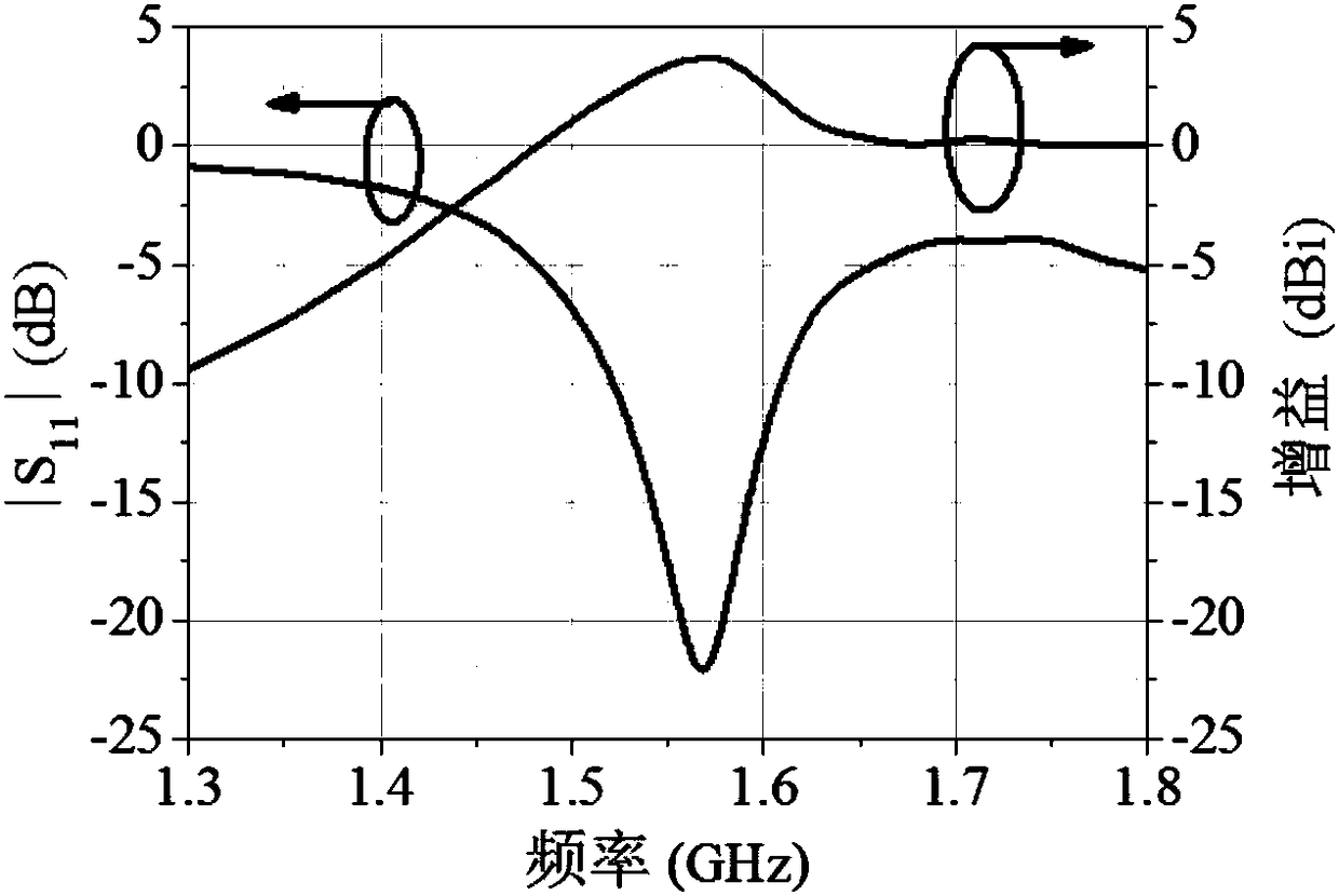
The invention provides a low-profile radial-line helical antenna comprising a coaxial line, a first metal layer, a first dielectric substrate, a second metal layer, a second dielectric substrate, and a third metal layer. The layers are laminated successively. A first helical line is formed at the first metal layer; a second helical line that is opposite to the first helical line and is coupled with the first helical line is formed at the second metal layer; the third metal layer is grounded; and the coaxial line passes through the first metal layer, the first dielectric substrate, the second metal layer, the second dielectric substrate, and the third metal layer successively. An outer conductor of the coaxial line is connected with the third metal layer electrically; and an inner conductor of the coaxial line is connected with an initial point of the first helical line electrically. According to the invention, on the basis of coupling between the second helical line and the first helical line, a phase requirement on the reflection path of the first helical line can be reduced and thus the distance requirement between the first helical line and the third metal layer can be reduced; the antenna size is reduced; and the low-profile radial-line helical antenna is realized.

Description

technical field [0001] The invention relates to the field of microwave technology, in particular to a low profile radial wire helical antenna. Background technique [0002] Since satellites work in space far away from the earth's atmosphere, the transmission of signals must go through the ionosphere and rain and fog layers. Ordinary linearly polarized antennas will be subjected to electromagnetic interference when passing through the ionosphere, causing the polarization direction to be deflected, or bit errors will occur due to factors such as rain and fog. Circularly polarized antennas can reduce the Ferrari rotation effect and multipath effect caused by the ionosphere, so circularly polarized antennas are generally used as transceiver antennas in satellite communications. Therefore, the design of circularly polarized antenna is very important. [0003] The radial wire helical antenna is an important non-resonant circularly polarized antenna, which is composed of a feed s...

Claims


Application Information

Patent Timeline
Patent Type & Authority Patents(China)
IPC IPC(8): H01Q1/38H01Q1/50H01Q7/00
CPCH01Q1/38H01Q1/50H01Q7/00
Inventor 施金张诚曹青华张威徐凯唐慧包志华
Owner 浙江恩碧技创新科技有限公司
Why Eureka
Try Eureka