Method and device for acquiring rotor position of direct-drive ball mill permanent magnet synchronous motor

A permanent magnet synchronous motor, rotor position technology, applied in the direction of electromechanical devices, electrical components, electric components, etc.

Active Publication Date: 2018-12-18
CHENGDU MAOYUAN TECH
View PDF5 Cites 0 Cited by
  • Summary
  • Abstract
  • Description
  • Claims
  • Application Information

AI Technical Summary

Problems solved by technology

[0005] The purpose of the present invention is to solve the problem of detection, information and conversion of the rotor position information of the permanent magnet synchronous motor of the direct-drive ball mill

Method used


Image

  • Method and device for acquiring rotor position of direct-drive ball mill permanent magnet synchronous motor
  • Method and device for acquiring rotor position of direct-drive ball mill permanent magnet synchronous motor
  • Method and device for acquiring rotor position of direct-drive ball mill permanent magnet synchronous motor

Examples


Embodiment 1

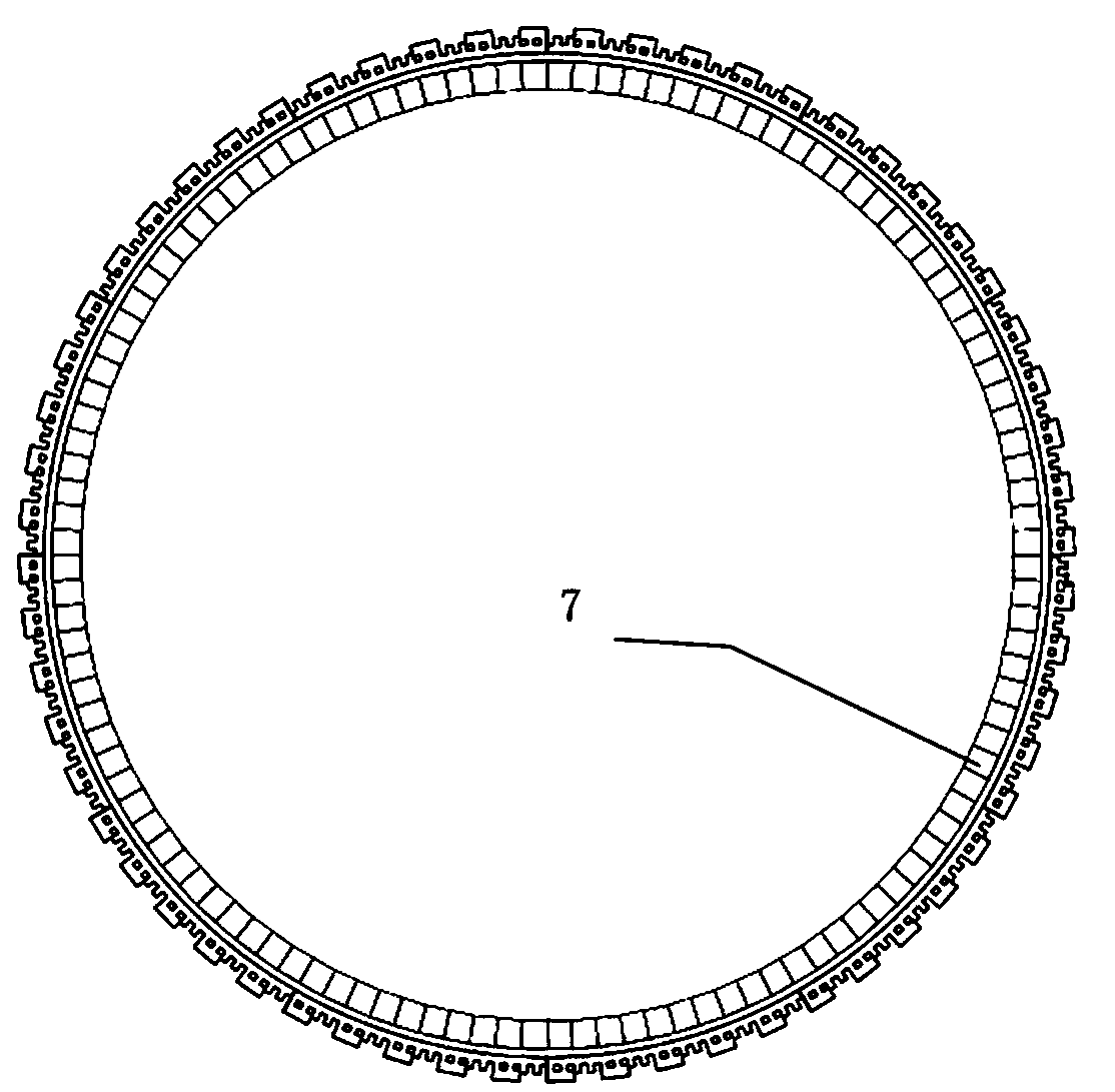
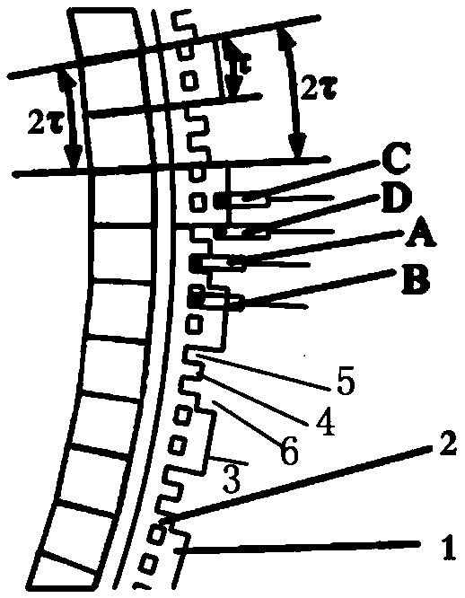
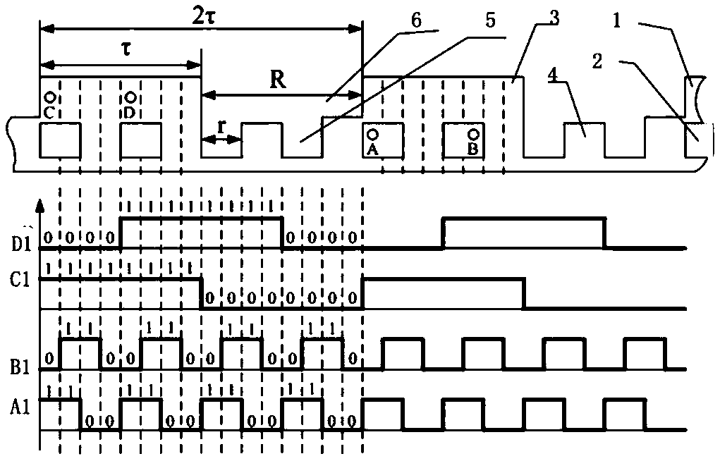
[0031] The direct-drive ball mill permanent magnet synchronous motor rotor position acquisition device includes a photoelectric detection unit. The photoelectric detection unit is connected with a position signal processing unit. The position signal processing unit is preferably an MCU. The photoelectric detection unit includes a photoelectric encoder disk and a photoelectric position detector. The position detector is installed on the stator, and the photoelectric encoder disk corresponding to the photoelectric position detector is installed on the rotor; figure 2 and image 3 It is shown that the edge of the photoelectric encoder disc is provided with an encoding ring corresponding to the photoelectric position detector, and the encoding ring includes an inner encoding ring 2 and an outer encoding ring 1; the inner encoding ring 2 includes the first fan ring imaginary part 5 and the first fan ring real part 5. The first fan ring imaginary part 5 and the first fan ring real ...


PUM


Abstract

The invention discloses a method for collecting the rotor position of a permanent magnet synchronous motor of a direct-drive type ball mill. The method comprises the steps that 1, a photoelectric detection unit is adopted for converting collected rotor position information into pulse signals to be output; 2, a position signal processing unit is adopted for encoding the pulse signals, and position information encoded signals are output; 3, the position information encoded signals are output to a ball mill controller. The device for collecting the rotor position of the permanent magnet synchronous motor of the direct-drive type ball mill comprises the photoelectric detection unit, the photoelectric detection unit is connected with the position signal processing unit and comprises a photoelectric encoding disc and a photoelectric position detector, and the device is characterized in that an encoding ring corresponding to the photoelectric position detector is arranged on the edge of the photoelectric encoding disc. The device is ingenious and simple in structure and low in cost.

Description

technical field [0001] The invention relates to the technical field of mine beneficiation equipment control, in particular to a method and a device for collecting the rotor position of a permanent magnet synchronous motor of a direct-drive ball mill. Background technique [0002] The ball mill is a kind of equipment for crushing materials. The traditional ball mill needs to set up a complicated transmission mechanism, and the motor drives the drum to rotate through the gearbox, open gears, etc. These transmission mechanisms not only occupy a large area, but also have transmission losses, which reduces the efficiency of the ball mill. The above-mentioned shortcomings can be overcome by adopting the direct drive method, where the rotor of the motor drives the drum directly. [0003] Considering the low speed and large inertia when the ball mill rotates, the permanent magnet synchronous rotating motor is the preferred solution, that is, the permanent magnet poles are installed...

Claims


Application Information

Patent Timeline
Patent Type & Authority Patents(China)
IPC IPC(8): H02K11/22
Inventor 王家璐陆可鞠林睿张霆郭冀岭
Owner CHENGDU MAOYUAN TECH
Why Eureka
Try Eureka