Boost-buck switch circuit and control method thereof

A switch circuit, buck-boost technology, applied to electrical components, conversion equipment without intermediate conversion to AC, output power conversion device, etc., can solve problems such as the complex circuit structure of the buck-boost switch circuit 10, and achieve mode switching Convenience, simple circuit structure and loop, and good stability

Active Publication Date: 2016-10-12
CHENGDU MONOLITHIC POWER SYST
View PDF5 Cites 11 Cited by
  • Summary
  • Abstract
  • Description
  • Claims
  • Application Information

AI Technical Summary

Problems solved by technology

In practical applications, the circuit structure of the buck-boost switch circuit 10 is very complicated.

Method used


Image

  • Boost-buck switch circuit and control method thereof
  • Boost-buck switch circuit and control method thereof
  • Boost-buck switch circuit and control method thereof

Examples


Embodiment Construction

[0029] Specific embodiments of the present invention will be described in detail below, and it should be noted that the embodiments described here are only for illustration, not for limiting the present invention. In the following description, numerous specific details are set forth in order to provide a thorough understanding of the present invention. It will be apparent, however, to one of ordinary skill in the art that these specific details need not be employed to practice the present invention. In other instances, well-known circuits, materials or methods have not been described in detail in order to avoid obscuring the present invention.

[0030] Throughout this specification, reference to "one embodiment," "an embodiment," "an example," or "example" means that a particular feature, structure, or characteristic described in connection with the embodiment or example is included in the present invention. In at least one embodiment. Thus, appearances of the phrases "in on...


PUM


Abstract

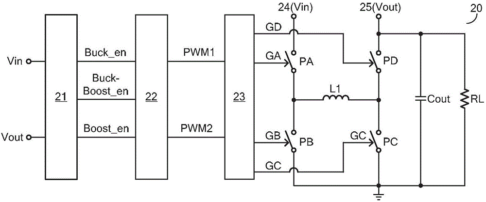
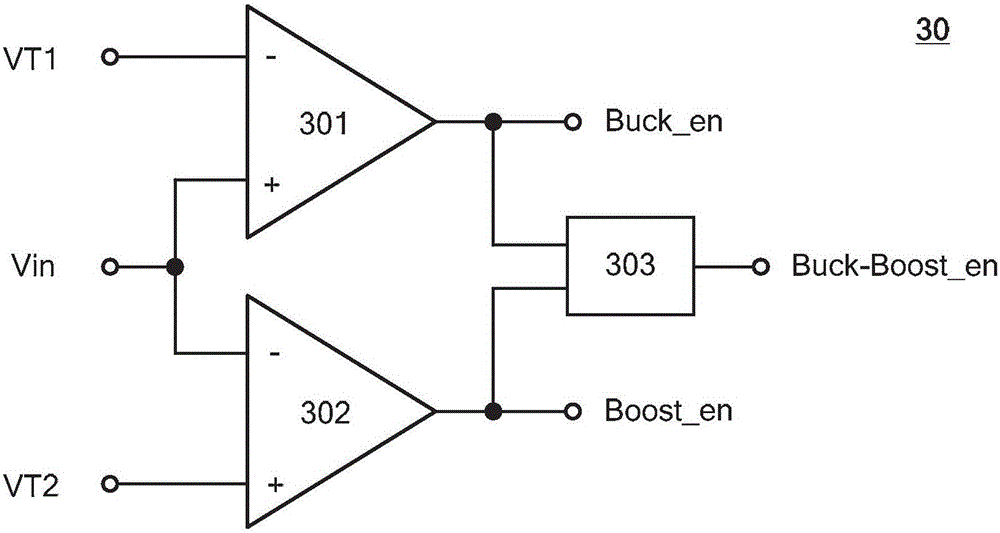
The invention provides a boost-buck switch circuit. According to the boost-buck switch circuit, under a buck mode, a fixed duration conduction circuit or a fixed duration off circuit is employed to control a buck switch pair; under a boost mode, the fixed duration conduction circuit or the fixed duration off circuit is employed to control a boost switch pair; under a boost-buck mode, the fixed duration conduction circuit or the fixed duration off circuit is employed to simultaneously control the buck switch pair and the boost switch pair. The boost-buck switch circuit employs a combined mode of voltage feedback and current feedback to realize constant voltage output and constant current output of a system and can be applied to a cell control system. The boost-buck switch circuit needs no loop compensation circuit, the circuit structure is simple, moreover, each work mode can be conveniently switched, seamless joint of each work mode can be realized, and relatively good transient characteristics are realized.

Description

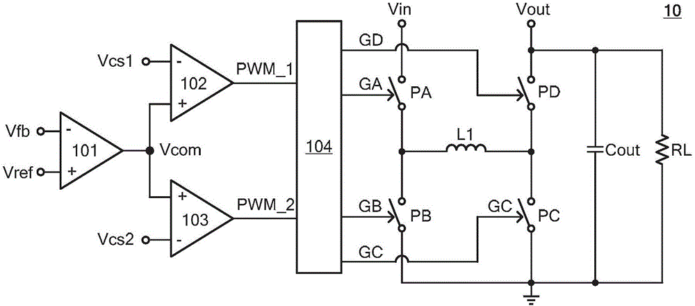
technical field [0001] The present invention relates to an electronic circuit, and more specifically, the present invention relates to a switch circuit and a control method thereof. Background technique [0002] The buck-boost switching circuit has three working modes: boost mode, buck mode and buck-boost mode. Normally, when the input voltage is higher than the output voltage, the buck-boost switching circuit works in buck mode; when the input voltage is lower than the output voltage, the buck-boost switching circuit works in boost mode; when the input voltage and output voltage When close, the buck-boost switch circuit works in the buck-boost mode. [0003] figure 1 A conventional buck-boost switching circuit 10 is shown. The buck-boost switch circuit 10 includes: a first power switch PA and a second power switch PB, coupled between the input voltage Vin and ground; a third power switch PC and a fourth power switch PD, coupled between the output voltage Between Vout an...

Claims


Application Information

Patent Timeline
Patent Type & Authority Applications(China)
IPC IPC(8): H02M3/10H02M1/14
CPCH02M1/14H02M3/10
Inventor 欧阳茜
Owner CHENGDU MONOLITHIC POWER SYST
Why Eureka
Try Eureka