Input selective smart bias tee

A signal input and filter technology, applied in the direction of antenna, antenna parts, electrical components, etc., can solve the problems of unusable and complicated smart biasers

Inactive Publication Date: 2016-10-12
COMMSCOPE TECH LLC
View PDF6 Cites 5 Cited by
  • Summary
  • Abstract
  • Description
  • Claims
  • Application Information

AI Technical Summary

Problems solved by technology

[0007] Utilizing SBTs to provide DC power and control signals to tower-mounted equipment becomes more complicated in the case of multi-band antennas. In particular, the current problem is that using standard antennas that utilize blind-mate, capacitively coupled, coaxial connectors There are certain advantages to the interface. However, capacitively coupled connectors are inherently incapable of transferring DC power through the connection interface due to the DC blocking properties, so conventional smart biasers cannot be used to transfer power to devices using this type of interface. Connectors on tower-mounted equipment. Correspondingly, more flexible structures are required for transmitting AISG control signals and DC power to RET antennas and other tower-mounted equipment.

Method used


Image

  • Input selective smart bias tee
  • Input selective smart bias tee
  • Input selective smart bias tee

Examples


Embodiment Construction

[0017] exist Figure 7 and 8 A wireless communication base station is shown in , and may include a remote radio head 60 , an interface 61 including an input selective smart biaser 62 , and a RET antenna 63 with an AISG controller 64 . Input selective SBT 62 includes RF input 65, RF output 66 to antenna 78, AISG input 67, and AISG output 68. Although "input" and "output" are used herein to refer to control from remote radio head 60 to RET antenna 63 data flow, but those of ordinary skill will understand that data transmission is bi-directional, and data also flows from the RET antenna 63 back to the remote radio head 60.

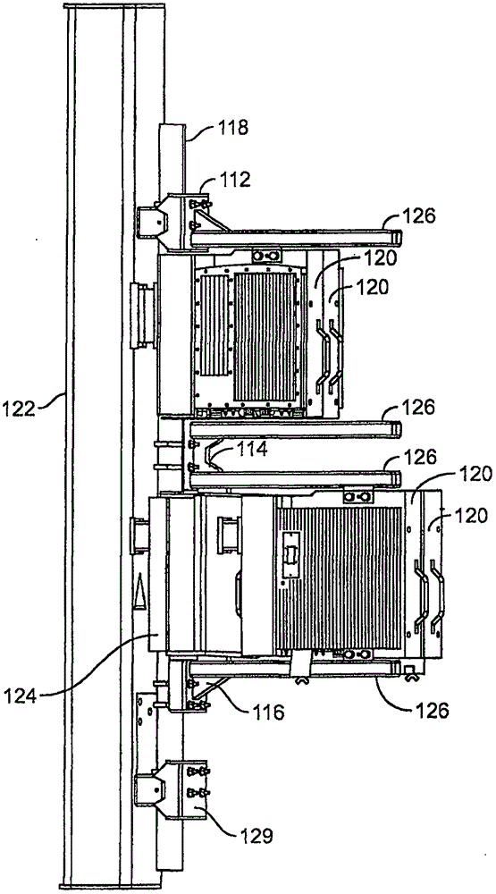
[0018] see image 3 , discloses one example of an antenna interface 110 that may be used in the present invention. In this example, upper tower mount 112 , and middle tower mount 114 and lower tower mount 116 are mounted on mounting rods 118 . The upper tower mount 112 , and the middle tower mount 114 and the lower tower mount 116 are configured to mechan...


PUM


Abstract

The Invention comprises a method and Interface for powering and controlling an antenna, having an RF signal input, an AISG signal input, including a DC current, wherein the RF signal input is coupled to the antenna by a filter, so the filter blocks a signal with DC current, and the AISG signal is coupled to the antenna through a switch, so that if an AISG signal is present, the switch automatically allows the AISG signal through to the antenna for control of the antenna, and if no AISG signal is present, the RF signal is automatically allowed through to the antenna for control of the antenna.

Description

[0001] This application claims priority to U.S. Provisional Application Serial No. 61 / 943,156, filed February 21, 2014. Background technique [0002] A Smart Bias Tee (SBT) is often used inside the antenna to allow power and control signals for the actuator to be delivered to the antenna via an RF coaxial cable rather than a separate multi-conductor cable. At the bottom, a first SBT puts power and control signals on the RF cable. At the top of the tower, a second SBT pulls it back off. See, for example, US Patent Application Publication No. 2007 / 0161348 ("348 Application"), which is incorporated herein by method. [0003] exist figure 1 A known application for SBT is shown in . The electrical downtilt of the antenna beam can be controlled by a remote electric tuning (RET) device 15. A base station can comprise three or more such tower mounted antennas. System 10 includes a control subsystem 16 that interfaces with RET 15, a radio 17 that interfaces with antenna 13, and a DC ...

Claims


Application Information

Patent Timeline
Patent Type & Authority Applications(China)
IPC IPC(8): H04W88/08
CPCH01Q1/246H01Q1/1228
Inventor R·K·巴特勒S·派特尔C·邦戴尔蒙特
Owner COMMSCOPE TECH LLC
Why Eureka
Try Eureka