Localization with non-synchronous emission and multipath transmission

A fixed position, transmission frequency technology used in illuminated areas with higher resolution images

Active Publication Date: 2016-10-26
MASSACHUSETTS INST OF TECH
View PDF4 Cites 4 Cited by
  • Summary
  • Abstract
  • Description
  • Claims
  • Application Information

AI Technical Summary

Problems solved by technology

As another example, in outdoor positioning in urban environments, signals may be reflected by buildings causing multipath effects

Method used


Image

  • Localization with non-synchronous emission and multipath transmission
  • Localization with non-synchronous emission and multipath transmission
  • Localization with non-synchronous emission and multipath transmission

Examples


Embodiment Construction

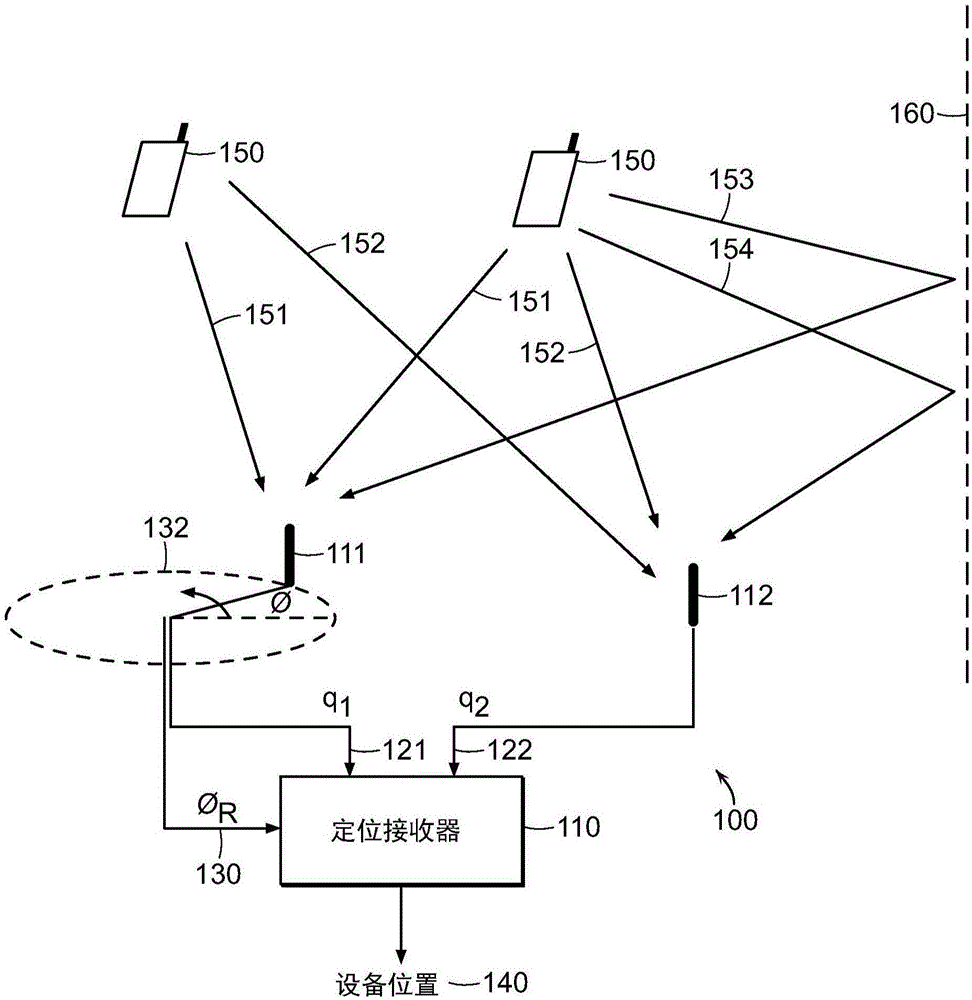
[0037] A number of methods are described below in the context of localization of radio frequency transmitting devices in indoor environments where the transmitting device is positioned independently of the receiver and where there are typically multiple reflection paths from the transmitting device to the receiver. Specific embodiments in which the sending device is a cellular phone (e.g., LTE transmissions in the 700MHz-2.6GHz range) or a wireless local area network device (e.g., IEEE 802.11 standard ("WiFi") transmissions at 2.4GHz or 5GHz) describe. It should be noted that the method to address the independence of the transmitting device and the positioning receiver and the method to address multipath effects can be used independently in various applications and together provide high accuracy in applications such as indoor positioning. For reference, the wavelengths of radio signals at 2.4Ghz and 5.0Ghz are approximately 12.5cm and 6.0cm, respectively.

[0038] A first embod...


PUM


Abstract

Directional characterization of a location of a target device makes use of multiple radio transmissions that are received from the target device. In some examples, each radio transmission is received at a first antenna at a fixed location, and is also received at a second moving antenna. The received transmissions are combined to determine the directional characterization, for example, as a distribution of power as a function of direction. In some examples, the received radio transmissions are processed to determine, for each of a plurality of directions of arrival of the radio transmissions, a most direct direction of arrival, for example, to distinguish a direct path from a reflected path from the target.

Description

[0001] Cross References to Related Applications [0002] This application claims U.S. Provisional Application No. 61 / 921,127, filed December 27, 2013, entitled "Synthetic ApertureRadar Between Independent Wireless Nodes," and the December 27, 2013 Claimed benefit of U.S. Provisional Application No. 61 / 921,190, filed entitled "Characterizing Multipath Delays in Antenna Array and Synthetic Aperture Radar Systems." The contents of these applications are hereby incorporated by reference. [0003] This application also relates to the invention titled "Characterizing MultipathDelays in Antenna Array and Synthetic Aperture Radar Systems (characterizing the multipath time delay in antenna arrays and synthetic aperture radar systems)" submitted at the same time as this application __ / ___, ___, U.S. Application No. (Attorney No. 70009-D37001). This application is hereby incorporated by reference. [0004] Statement Regarding Federally Sponsored Research [0005] This invention was mad...

Claims


Application Information

Patent Timeline
Patent Type & Authority Applications(China)
IPC IPC(8): G01S3/14G01S3/46G01S3/48G01S3/52G01S3/72G01S13/48G01S13/90
CPCG01S3/14G01S3/46G01S3/48G01S3/52G01S3/72G01S13/48G01S13/9023G01S13/9082G01S3/04G01S5/0273H04L27/2601H04W64/00G01S19/14G01S19/24
Inventor 斯沃若恩·苏雷什·库玛尔迪纳·卡塔比
Owner MASSACHUSETTS INST OF TECH
Why Eureka
Try Eureka