Mechanical lock telescopic baton utilizing lamp tube as button

A telescopic baton and mechanical lock technology, which is applied to batons, weapons without explosives, parts of lighting devices, etc., can solve the problems of increasing the volume of the batons, loose and deformed internal components, inconvenient to carry and use, etc., and achieves good fixing effect. The effect of free shrinkage and simple structure

Active Publication Date: 2016-11-09
关敏婷
View PDF4 Cites 3 Cited by
  • Summary
  • Abstract
  • Description
  • Claims
  • Application Information

AI Technical Summary

Problems solved by technology

This structure is time-consuming and labor-intensive for repeated use of the telescopic function, and when pressing down, it is necessary to find a flat and hard plane and try to keep the baton in a perpendicular state to the plane, otherwise the baton will easily slip and hit the user, and it will be compressed repeatedly in this way The baton will loosen and deform the internal components, and the pipe fittings will lose their locking function and can be stretched out or retracted naturally under gravity, making the baton ineffective
[0004] In addition, in the existing retractable batons, in order to facilitate the execution of tasks at night, lights are provided, but the lights only have the function of lighting, and cannot be used as unlocking buttons to realize the unlocking and contraction of the baton, which will increase the size of the baton to a certain extent. The volume makes it inconvenient to carry and use

Method used


Image

  • Mechanical lock telescopic baton utilizing lamp tube as button
  • Mechanical lock telescopic baton utilizing lamp tube as button
  • Mechanical lock telescopic baton utilizing lamp tube as button

Examples


Embodiment Construction

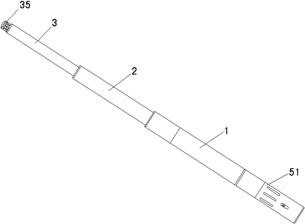
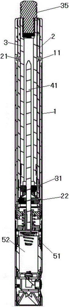
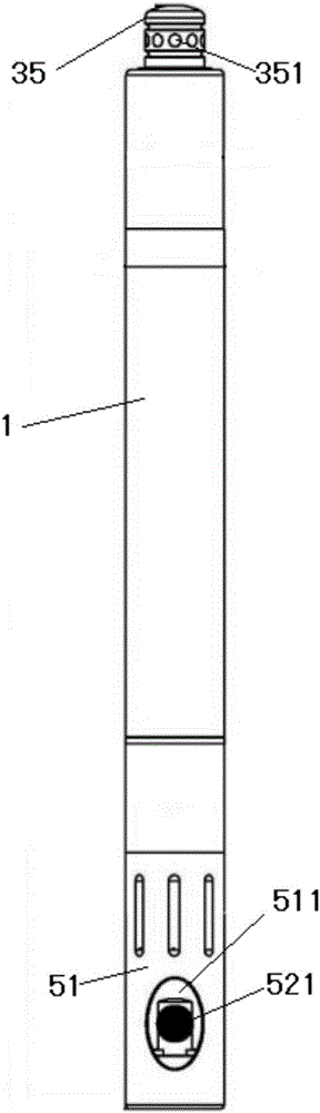
[0024] see Figure 1-12 As shown, the present invention relates to a telescopic baton with a mechanical lock using a lamp tube as a button, which includes a hollow handle tube 1, a middle tube 2, and a top tube 3, and the middle tube 2 and top tube 3 are sequentially arranged on the handle Inside the tube 1, which also includes a release mechanism and a lamp set, the tail ends of the middle end tube 2 and the top end tube 3 are respectively provided with middle end snap locks that extend elastically along the outer direction of the diameter of the middle end tube 2 and the top end tube 3 1. Top locking, the front end of the handle tube 1 and the front end of the middle tube 2 are provided with a first locking groove 11 and a second locking groove 21 corresponding to the middle locking and the top locking, and the release mechanism includes A release lever 41, a positioning cover 42, and a push button 43 are used to shrink the middle-end latch and the top-end latch respectively...


PUM


Abstract

A mechanical lock telescopic baton utilizing a lamp tube as a button comprises a hollow handle pipe, a middle end pipe and a top end pipe and further comprises a releasing mechanism and a lamp tube external member. A middle end clamp lock is arranged at the tail end of the middle end pipe, and a top end clamp lock is arranged at the tail end of the top end pipe. A first clamp groove and a second clamp groove which correspond to the middle end clamp lock and the top end clamp lock are formed in the front end of the handle pipe and the front end of the middle end pipe correspondingly. The releasing mechanism comprises a releasing rod, a positioning cover and a retractable pressing part. One end of the releasing rod is fixed to one end of the positioning cover. The retractable pressing part is arranged at the other end of the positioning cover through a spring. The releasing rod is arranged in the handle pipe and fixedly arranged at the tail end of the handle pipe through the positioning cover. The lamp tube external member comprises a hollow fixing sleeve and the lamp tube, wherein the lamp tube is movably arranged in the hollow fixing sleeve, and the front end of the hollow fixing sleeve is in threaded connection with the tail end of the handle pipe. The tail end of the lamp tube abuts against the retractable pressing part, and a lighting lamp at the other end of the lamp tube is limited through the edge at the tail end of the hollow fixing sleeve.

Description

technical field [0001] The invention relates to the field of batons, in particular to a telescopic baton with a mechanical lock using a lamp tube as a button. Background technique [0002] Baton is a commonly used police equipment. In general batons, the length is fixed, which makes it inconvenient to carry, so there is a retractable baton. [0003] The telescopic baton is made of multi-section pipe fittings that are nested together. When in use, the pipe is pulled out or thrown out. When retracting, the head of the baton needs to be pressed down against the plane to press the pipe into shrinkage. This structure is time-consuming and labor-intensive for repeated use of the telescopic function, and when pressing down, it is necessary to find a flat and hard plane and try to keep the baton in a perpendicular state to the plane, otherwise the baton will easily slip and hit the user, and it will be compressed repeatedly in this way The baton will loosen and deform the internal...

Claims


Application Information

Patent Timeline
Patent Type & Authority Applications(China)
IPC IPC(8): F41B15/02F21V33/00
CPCF21V33/0076F41B15/027
Inventor 曾澤輝
Owner 关敏婷
Why Eureka
Try Eureka