A power supply equipment monitoring system

A technology of power supply equipment and monitoring system, applied in the direction of circuit devices, electrical components, etc., can solve the problem of low intelligence in power supply, achieve the effect of intelligent deployment and meet differentiated needs

Inactive Publication Date: 2019-02-05
安徽众升电力科技有限公司
View PDF4 Cites 0 Cited by
  • Summary
  • Abstract
  • Description
  • Claims
  • Application Information

AI Technical Summary

Problems solved by technology

[0005] The invention proposes a monitoring system for power supply equipment, which solves the problem of low intelligence in power supply in the prior art, and it is difficult to meet the differentiated demand for power in different regions

Method used


Image

  • A power supply equipment monitoring system

Examples


Embodiment Construction

[0019] The technical solutions in the embodiments of the present invention will be clearly and completely described below in conjunction with the accompanying drawings in the embodiments of the present invention. Obviously, the described embodiments are only a part of the embodiments of the present invention, rather than all the embodiments. Based on the embodiments of the present invention, all other embodiments obtained by those of ordinary skill in the art without creative work shall fall within the protection scope of the present invention.

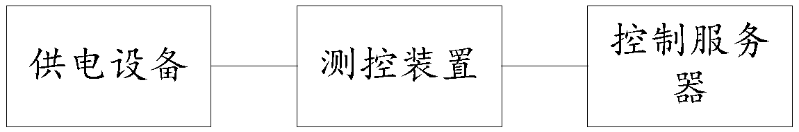
[0020] Such as figure 1 As shown, the power supply equipment monitoring system includes a control server, the control server is remotely connected to a measurement and control device, the measurement and control device is connected to a power supply device, and the measurement and control device monitors the working parameters of the power supply device in real time and monitors information in real time Using the transmission to the cont...


PUM


Abstract

The invention provides a power supply equipment monitoring system, which comprises a control server and is characterized in that the control server is remotely connected to a measurement and control device, the measurement and control device is connected to power supply equipment, the measurement and control device monitors operating parameters of the power supply equipment in real time and transmits monitoring information to the control server in real time, and the control server remotely control on or off of part power supply equipment according to the received operating parameters. The power supply equipment monitoring system can realize intelligent allocation of the electricity quantity, and differentiated demands for the electricity quantity of different regions at different time periods are satisfied.

Description

Technical field [0001] The invention belongs to the technical field of power monitoring, and particularly relates to a power supply equipment monitoring system. Background technique [0002] At present, in the field of electric power technology, different regions usually have different demand for electricity in different time periods. For example, when there is a region in the peak period of electricity usage, the demand for electricity in another region may not be high, or there may be a region. When the demand for electricity in a certain time period is different from that in other time periods, for this similar situation, manual control is generally used to realize the regulation of electricity in different regions and different time periods, through the switch or the switch Realize the deployment of electricity. [0003] However, this method requires extra manual operation, low work efficiency, and poor flexibility. [0004] Therefore, there is an urgent need for a power supply...

Claims


Application Information

Patent Timeline
Patent Type & Authority Patents(China)
IPC IPC(8): H02J13/00
CPCH02J13/0013
Inventor 孙文传
Owner 安徽众升电力科技有限公司
Why Eureka
Try Eureka