
Sensor pipeline automatic compression molding device

An automatic compression molding and sensor tube technology, applied in the field of plastic processing, can solve the problems of lower production efficiency, difficulty in separating and cleaning sensor tubes, easy adhesion of sensor tubes, etc., and achieve the effect of easy operation

Active Publication Date: 2019-04-30
江苏勇易机械制造有限公司
View PDF6 Cites 0 Cited by
  • Summary
  • Abstract
  • Description
  • Claims
  • Application Information

AI Technical Summary

Problems solved by technology

[0004] After compression molding, each sensor pipeline is easy to stick, and the sensor pipelines after adhesion are mainly separated manually, which is easy to reduce production efficiency, and it is time-consuming and laborious to work. In the long run, the production cost is high. Sometimes each sensor It is also difficult to separate the pipelines cleanly, and it is easy to leave burrs on the sensor pipeline

Method used


Image

  • Sensor pipeline automatic compression molding device
  • Sensor pipeline automatic compression molding device
  • Sensor pipeline automatic compression molding device

Examples


Embodiment 1

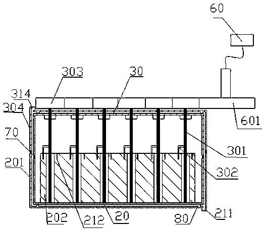
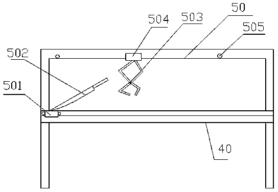
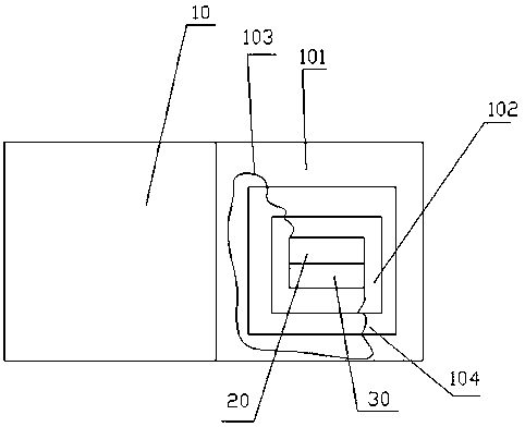
[0023] Example 1 is basically as attached figure 1 , Attached figure 2 And image 3 Shown: an automatic compression molding device for sensor pipelines, including a shearing device, a compression molding device, and a compression molding machine 10.

[0024] The shearing device includes a worktable 40, a cutter 502, a clamping jaw 503 and a slide rail. The slide rail includes a slide rail seat 50, a ball-shaped rolling element, a first sliding plate 501 and a second sliding plate 504, and the rolling element is installed on the first sliding plate. 501 and the second sliding plate 504, the workbench 40 is provided with two upper and lower slide rail seats 50, the second slide plate 504 is installed on the slide rail seat 50 erected on the workbench 40, and the second slide plate 504 is installed Two locking screws 505 are installed on the slide rail seat 50 of the slide rail to limit the sliding displacement of the gripper 503; the slide rail installed on the workbench 40 is ins...


PUM


Abstract

The invention relates to the field of plastic machining, and in particular, discloses a sensor pipeline automatic compression molding device. The device comprises a shearing device, a compression molding device and a compression molding machine; the shearing device includes a worktable, a cutter and a slide rail; the slide rail includes a slide rail base, a rolling body, a first slide plate and a second slide plate; the cutter is hinged to the first slide plate; the slide rail base is fixedly mounted on the worktable; the compression molding device includes a fixed pressing plate and a movable pressing plate; multiple molding cavities are formed in the fixed pressing plate; cutting grooves are formed between two adjacent molding cavities; multiple molding shafts capable of rotating are mounted in the fixed pressing plate; rotating parts integrally molded with the molding shafts are arranged at the upper ends of the molding shafts, and are positioned on the upper surface of the fixed pressing plate; the molding shafts are opposite to the molding cavities; and cutting machines are opposite to the cutting grooves. The device performs four procedures of shearing, melting, compression molding and final separation for plastic plates to finish a series of machining of sensor pipelines.

Description

Technical field [0001] The invention belongs to the field of plastic processing, and particularly relates to an automatic compression molding device for sensor pipelines. Background technique [0002] In order to obtain information from the outside world, people rely solely on their own sensory organs, which cannot fully understand the actual situation. To adapt to this situation, sensors are needed. Sensors have been widely used in all aspects of life, such as railway transportation, intelligent buildings, production automation, aerospace and many other fields. [0003] The manufacture of the sensor is not only the manufacture of its steel structure, but also the manufacture of the sensor pipeline. The material of the sensor pipeline is usually made of plastic sheets, which are melted and then compression molded. The manufacturing accuracy of the sensor pipeline is required to be high, and its accuracy is mainly affected by the amount of sheared plastic sheet. [0004] After compr...

Claims


Application Information

Patent Timeline
Patent Type & Authority Patents(China)
IPC IPC(8): B29C43/02B29C43/40B29L23/00
CPCB29C43/02B29C43/40B29C2043/403B29L2023/00
Inventor 涂国荣徐飞林锋周玉明涂鑫豪
Owner 江苏勇易机械制造有限公司
Learn More