Inflatable deployment periodical capsule valve type reducer and curling, folding and collecting method of inflatable deployment periodical capsule valve type reducer

A technology of periodic capsule flaps and inflatable deployment, which is applied in the system of spacecraft returning to the earth's atmosphere, the landing device of spacecraft, etc. It can solve the problems of low lift-to-drag ratio, poor outer edge stability, and small surface area. The effect of improving lift-drag ratio, improving stability and increasing surface area

Active Publication Date: 2016-11-16
HARBIN INST OF TECH
View PDF6 Cites 16 Cited by
  • Summary
  • Abstract
  • Description
  • Claims
  • Application Information

AI Technical Summary

Problems solved by technology

In order to ensure the safe landing of the spacecraft, the entry section is very important to the deceleration process of the spacecraft. The inflatable reducer can increase the resistance area of ​​the spacecraft by inflating it. It has many advantages such as small carrying volume, light weight, and easy to fold. However, the existing inflatable deployment reducers still have problems such as small lower surface area per unit volume, complex gas flow path, low lift-to-drag ratio, and poor stability of the outer edge, which need to be optimized and solved.

Method used


Image

  • Inflatable deployment periodical capsule valve type reducer and curling, folding and collecting method of inflatable deployment periodical capsule valve type reducer
  • Inflatable deployment periodical capsule valve type reducer and curling, folding and collecting method of inflatable deployment periodical capsule valve type reducer
  • Inflatable deployment periodical capsule valve type reducer and curling, folding and collecting method of inflatable deployment periodical capsule valve type reducer

Examples


Embodiment Construction

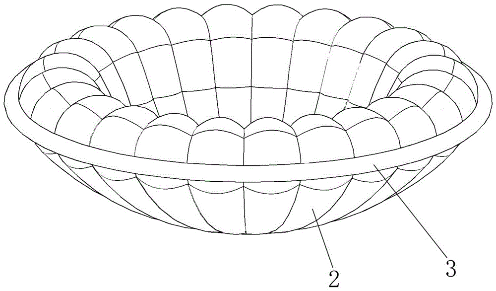
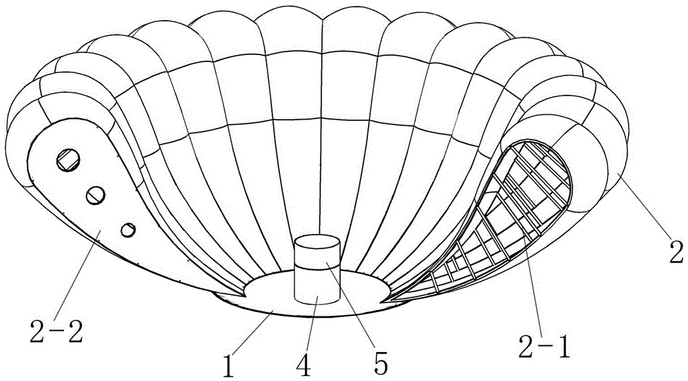
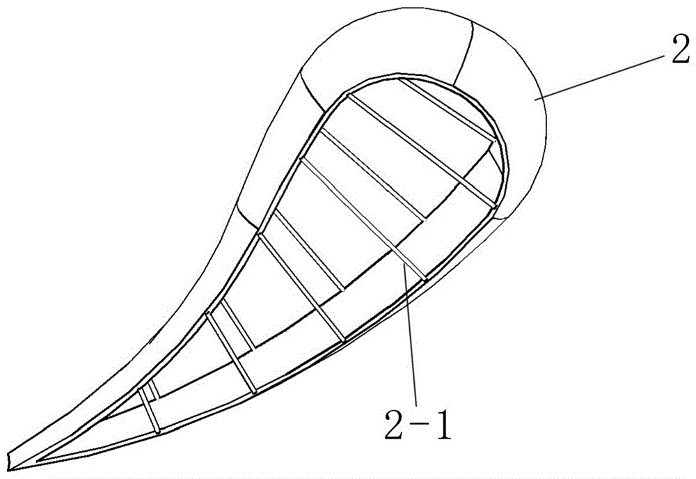
[0021] refer to Figure 1 to Figure 8 , an air-deployed periodic capsule-valve reducer, which includes a spherical segment-shaped rigid nose cone 1, and an umbrella-shaped airbag 2 composed of periodic capsule valves is arranged around the rigid nose cone 1. The airbag 2 is formed by the lower Upstairs expands outward along a parabola to form an outer surface with variable curvature. A group of tension cables 2-1 are arranged along the seams of every two adjacent flaps in the airbag 2, and a set of tension cables 2-1 is arranged around the largest diameter of the airbag 2. A spoiler air ring 3, the lower end of the airbag 2 is fixedly connected to the rigid nose cone 1, the rigid nose cone 1, the tension cable 2-1 and the spoiler air ring 3 jointly constrain the aerodynamic shape of the airbag 2; the spoiler air ring 3 and the airbag 2 It can be inflated and expanded in the air by connecting with the gas cylinder and the inflation control system; a horizontal center of mass co...


PUM


Abstract

The invention provides an inflatable deployment periodical capsule valve type reducer and a curling, folding and collecting method of the inflatable deployment periodical capsule valve type reducer and belongs to the technical field of reducers used by entry type spacecrafts for entering orbits. The problems existing in existing inflatable deployment reducers are solved. The inflatable deployment periodical capsule valve type reducer comprises a spherical-segment-shaped rigid head cone. An umbrella-shaped air bag composed of periodical capsule valves is arranged around the rigid head cone and expands to the outer side along a parabola from bottom to top to form the outer surface with the variable curvature. A set of stretching ropes are arranged at the position of a seam between every two adjacent capsule valves in the air bag. A flow turbulence air ring is arranged around the position with the largest diameter of the air bag. A horizontal mass center control disc is arranged on the inner side of the rigid head cone. An installation and insertion box is further arranged on the inner side of the rigid head cone. According to the curling, folding and collecting method of the inflatable deployment periodical capsule valve type reducer, W-shaped and start-shaped centripetal collecting manners are adopted to be combined with an annular winding method to fold the reducer, and the reducer and the method are used for deceleration of the spacecrafts.

Description

technical field [0001] The invention belongs to the technical field of speed reducers used by entering spacecraft to enter orbit, and in particular relates to an inflatable and unfolded periodic bag-valve type speed reducer and a curling, folding and folding method thereof. Background technique [0002] Spacecraft entry technology is an important technology, which is currently mastered by only a few countries; the process of spacecraft entry can generally be divided into the following stages: 1. Departing from the original orbit; Entering the atmosphere; 4. The entry section of turning into the orbit; 5. The landing section of turning into the orbit; 6. The safe landing of the spacecraft. In order to ensure the safe landing of the spacecraft, the entry section is very important to the deceleration process of the spacecraft. The inflatable reducer can increase the resistance area of ​​the spacecraft by inflating it. It has many advantages such as small carrying volume, light ...

Claims


Application Information

Patent Timeline
IPC IPC(8): B64G1/62
CPCB64G1/62
Inventor 卫剑征李盾陈强牛国强丛琳谭惠丰林国昌
Owner HARBIN INST OF TECH
Why Eureka
Try Eureka