Antitheft opening mechanism used for automatic door lock
An opening mechanism and automatic lock technology, which can be applied to building locks, building structures, buildings, etc., and can solve problems such as lock tongues that cannot be unlocked normally
- Summary
- Abstract
- Description
- Claims
- Application Information
AI Technical Summary
Problems solved by technology
Method used
Image
Examples
Embodiment 1
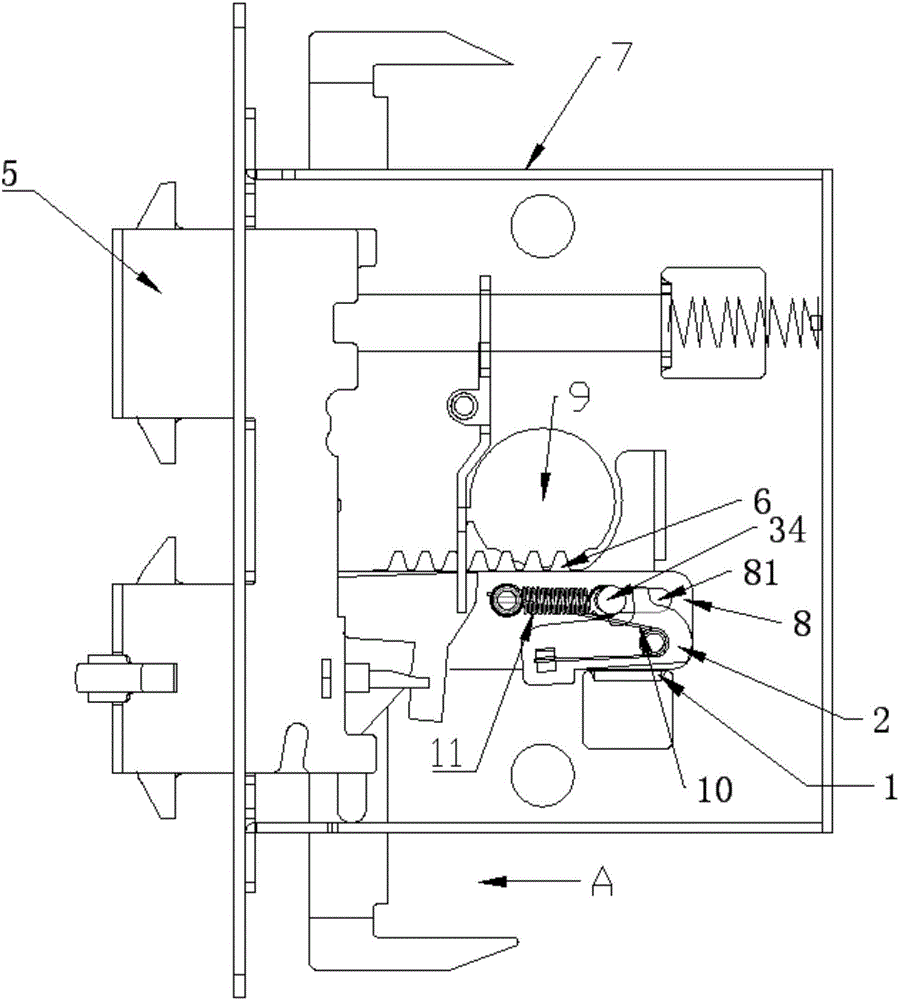
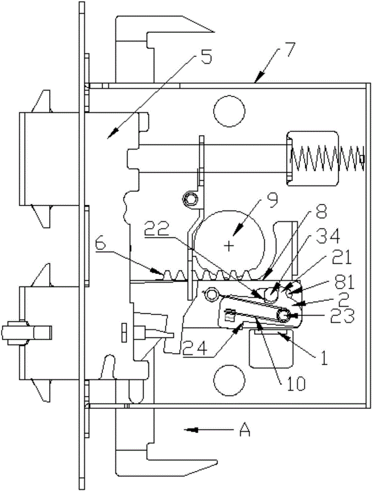
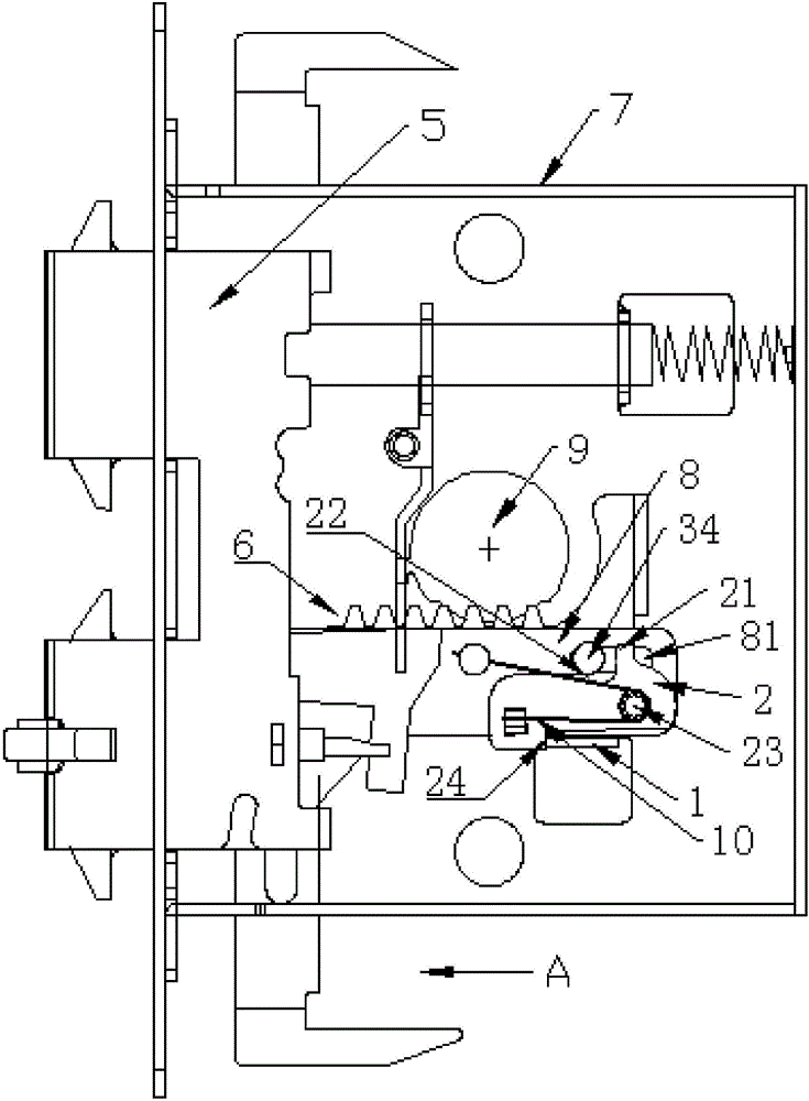
[0031] Figure 1-4Shown is a schematic structural diagram of the anti-theft opening mechanism used in the automatic lock described in this embodiment, including a resisting part 1, a locking part 2 and an unlocking part 3, and a stopper is provided in linkage with the unlocking part 3 Part 4, the unlocking part 3 and the stopper 4 in this embodiment are combined into one to become an unlocking pin 34; the conflicting part 1 is fixed on the lock housing 7, and the conflicting part 1 in this embodiment 1 is a stamped section with the bottom of the lock case 7 turned upward; the locking part 2 is movably arranged on the transmission main body part 8 fixedly connected with the lock tongue member 5, and passes through the engaging edge 24 of the locking part 2 Engagement with the contradictory piece 1 produces a tendency to prevent the unlocking movement of the bolt member 5; the unlocking pin 34 is reciprocally slidably arranged on the transmission body part 8 along the direction ...
Embodiment 2
[0042] Figure 7 Shown is the anti-theft opening mechanism for automatic locks described in this embodiment, including a conflicting member 1, a locking member 2 and an unlocking member 3, the conflicting member 1 is fixed on the lock case 7, in this embodiment The conflicting piece 1 is a stamped section with the bottom of the lock case 7 turned upward; the locking part 2 is movably arranged on the transmission main body part 8 fixedly connected with the lock tongue member 5, through which the locking part 2 The engagement of the engaging edge 24 of the contact member 1 with the blocking member 1 produces a tendency to prevent the unlocking movement of the bolt member 5; the unlocking member 3 is reciprocally slidably arranged on the transmission body part 8 along the direction in which the bolt extends, And driven by the unlocking force output part 6 of the lock head 9, the unlocking force output part 6 in this embodiment is a rack; the unlocking part 3 moves along the slidi...
PUM
 Abstract
Description
Claims
Application Information
 - R&D
- Intellectual Property
- Life Sciences
- Materials
- Tech Scout
- Unparalleled Data Quality
- Higher Quality Content
- 60% Fewer Hallucinations
Browse by: Latest US Patents, China's latest patents, Technical Efficacy Thesaurus, Application Domain, Technology Topic, Popular Technical Reports.
© 2025 PatSnap. All rights reserved.Legal|Privacy policy|Modern Slavery Act Transparency Statement|Sitemap|About US| Contact US: help@patsnap.com


