
L type simplified acoustic vector sensor array multi-parameter joint estimation quaternion method

An acoustic vector sensor and joint estimation technology, which is applied in the field of signal processing and can solve the problems that the vector characteristics of the acoustic vector sensor are not fully utilized, and the acoustic vector sensor array is blurred.

Active Publication Date: 2016-11-23
国骄胶粘新材料产业园管理有限公司
View PDF3 Cites 6 Cited by
  • Summary
  • Abstract
  • Description
  • Claims
  • Application Information

AI Technical Summary

Problems solved by technology

However, the existing quaternion model does not utilize the information between the sub-arrays, but only utilizes the information of the array space steering vector, and the vector characteristics of the acoustic vector sensor have not been fully utilized. The present invention constructs the acoustic pressure sensor and the x-axis, y-axis The new quaternion model of the simplified acoustic vector sensor composed of the vibration velocity sensor solves the phase ambiguity problem of the sparse L-shaped acoustic vector sensor array and improves the parameter estimation accuracy

Method used

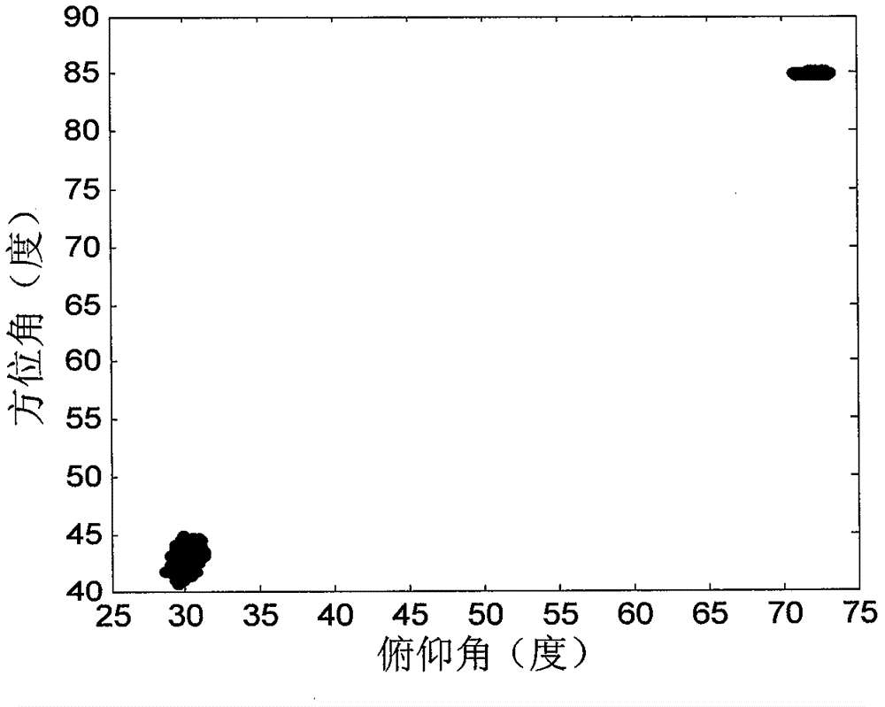
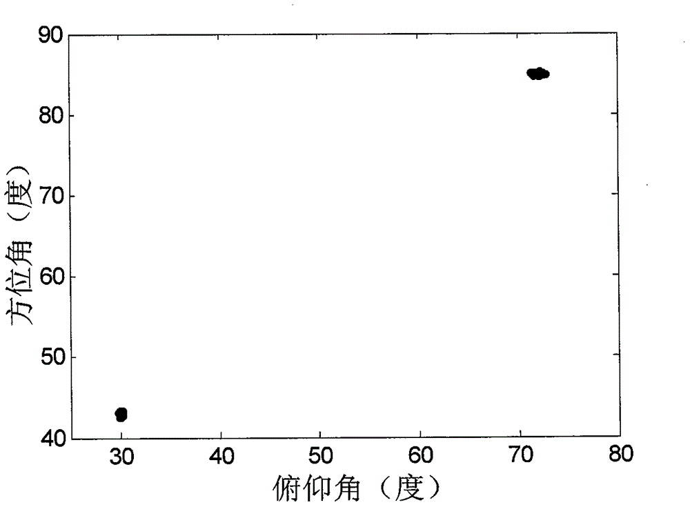
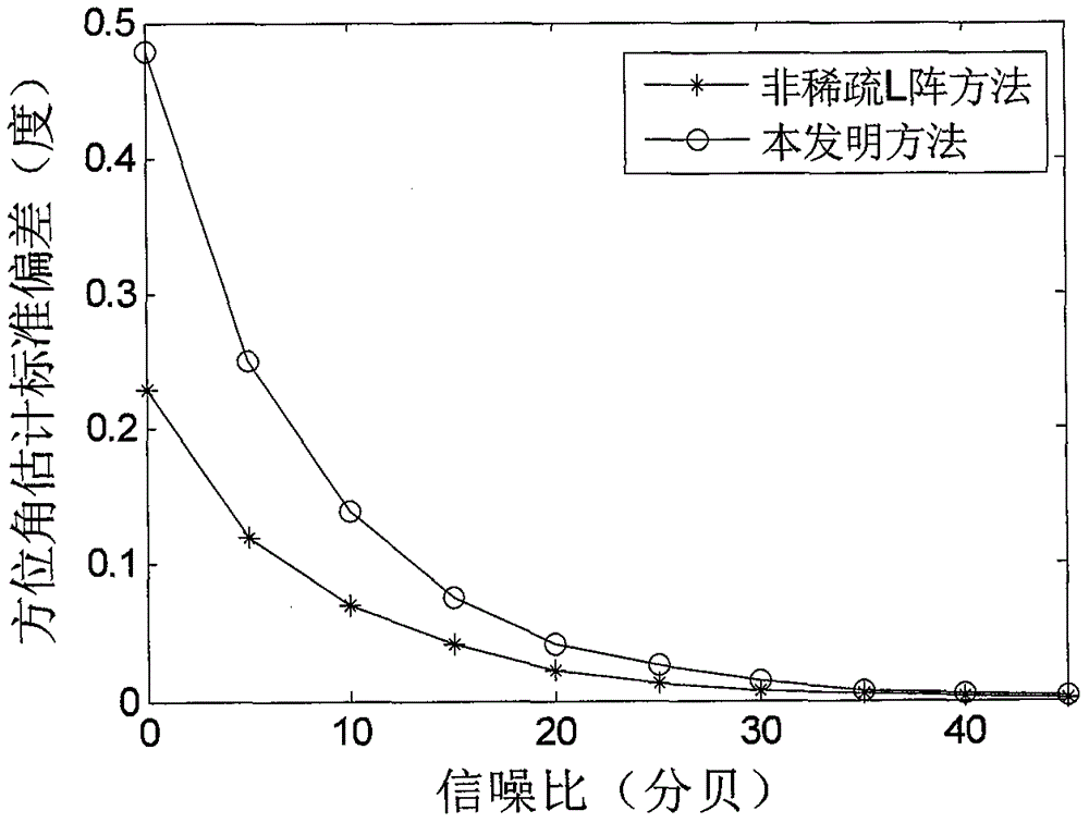

Image

  • L type simplified acoustic vector sensor array multi-parameter joint estimation quaternion method
  • L type simplified acoustic vector sensor array multi-parameter joint estimation quaternion method
  • L type simplified acoustic vector sensor array multi-parameter joint estimation quaternion method

Examples


Embodiment Construction

[0041] In order to make the above and other objects, features and advantages of the present invention more apparent, the following specifically cites the embodiments of the present invention, together with the accompanying drawings, for a detailed description as follows.

[0042] figure 1 Shown is a schematic diagram of an acoustic vector sensor array according to an embodiment of the present invention. The acoustic vector sensor array of the present invention is composed of N array elements arranged at equal intervals on the x-axis and N array elements arranged at equal intervals on the y-axis. The array elements on the coordinate origin share two axes, so the entire array has a total of 2N -1 array element, N is the number of array elements on the x-axis (or y-axis), which can be any integer, and the distance between array elements on the x-axis is d x , the distance between array elements on the y-axis is d y , the spacing d between array elements on the x-axis x and the...


PUM


Abstract

The invention relates to an L type simplified acoustic vector sensor array multi-parameter joint estimation quaternion method. According to the method, an array receives K far-field and uncorrelated narrow-band acoustic signals with different frequencies; two groups of data received by the array are superposed according to the sound pressure of the same array element as well as vibration velocities in the direction of an x axis and the direction of a y axis so as to form full-array receiving quaternion data; autocorrelation matrix feature decomposition is carried out on the data, so that the estimated value of an array steering vector is obtained; the estimation of sub-array steering vectors is reconstructed according to the estimated value of the array steering vector, and the rough estimated value of the direction cosine of the signals is obtained according to the rotation invariant relation of the sub-array steering vectors; and the translation invariant relationship matrix of sub-arrays on the x axis and the y axis can be obtained through using the translation invariant relationship of the sub-arrays on the x axis and the y axis, and the phase cycle fuzzy number of the translation invariant relationship matrix in the direction of the x axis and the direction of the y axis is determined according to the rough estimated value of the direction cosine, and therefore, the accurate estimated values of an azimuth angle and a pitch angle can be obtained. With the method of the invention adopted, the orthogonality between the components of an acoustic vector sensor can be kept, and better model error robustness can be achieved.

Description

technical field [0001] The invention belongs to the technical field of signal processing, in particular to a method for estimating the angle of arrival of a simplified acoustic vector sensor array. Background technique [0002] Determining the direction of arrival of sound waves is an important application of acoustic signal processing. The traditional method of measuring the direction of arrival of sound waves is to use an array of sound pressure sensors to spatially sample the sound field and estimate the spatial spectrum. In fact, sound waves are vector signals with scalar fields and vector fields. Traditional sound pressure sensors only use sound pressure information. Acoustic vector sensors have many advantages of direction sensitivity and large amount of measurement information, so they are increasingly widely used. . Acoustic vector sensors are divided into full acoustic vector sensors and simplified acoustic vector sensors. The full acoustic vector sensor is compos...

Claims


Application Information

Patent Timeline
Patent Type & Authority Applications(China)
IPC IPC(8): G01S3/802G01S3/808
Inventor 王桂宝傅明星
Owner 国骄胶粘新材料产业园管理有限公司
Learn More