Reference light source transmitting system, method, optical signal transmitting system and positioning system

A transmission system and signal transmission technology, applied in the field of positioning, can solve the problems of positioning signal interference and positioning space areas that cannot be located

Active Publication Date: 2020-01-14
BEIJING G WEARABLES INFORMATION SCI & TECH
View PDF6 Cites 0 Cited by
  • Summary
  • Abstract
  • Description
  • Claims
  • Application Information

AI Technical Summary

Problems solved by technology

Among them, in order to make the signals emitted by the calibration light source and the positioning beam emitting device be received by the laser receiving sensor on the object to be positioned, the calibration beam is usually set close to the positioning beam transmitting device, and in order to make the calibration signal sent by the calibration beam To fully cover the entire positioning space, it is necessary to increase the strength of the calibration signal sent by the calibration light source, and too strong a calibration signal will interfere with the positioning signal in the vicinity of the positioning beam emitting device, which may cause some areas of the positioning space to be unable to be located occurrence of phenomenon

Method used


Image

  • Reference light source transmitting system, method, optical signal transmitting system and positioning system
  • Reference light source transmitting system, method, optical signal transmitting system and positioning system
  • Reference light source transmitting system, method, optical signal transmitting system and positioning system

Examples


Embodiment Construction

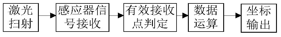
[0022] Preferred embodiments of the present disclosure will be described in more detail below with reference to the accompanying drawings. Although preferred embodiments of the present disclosure are shown in the drawings, it should be understood that the present disclosure may be embodied in various forms and should not be limited to the embodiments set forth herein. Rather, these embodiments are provided so that this disclosure will be thorough and complete, and will fully convey the scope of the disclosure to those skilled in the art.

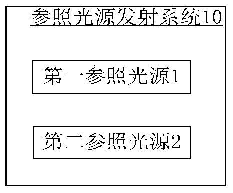
[0023] The present invention firstly provides a reference light emitting system suitable for being installed in a positioning space for assisting positioning. Wherein, the positioning space here may be one positioning space, or a plurality of expanded positioning spaces, and the shape of the positioning space may be a regular quadrilateral area such as a rectangle or a rhombus, or other irregular polygonal areas. figure 2 A schematic block...


PUM


Abstract

The invention discloses a reference light source emission system, a method, and a positioning system for facilitating the positioning operation. A first reference light source emits a first reference light pulse into a first effective illumination range. A second reference light source is separated from the first reference light source and emits a second reference light pulse into a second effective illumination range. The second reference light source and the first reference light source simultaneously emit the reference light pulses. The horizontal position of the first reference light source is located outside the field-angle direction range of a second fan-shaped region. The horizontal position of the second reference light source is located inside the range of a first fan-shaped region. The first effective illumination range and the second effective illumination range are combined to cover the space of the second reference light source within a predetermined distance range. Therefore, the first reference light source and the second reference light source are separated from each other and the effective irradiation range of the reference light pulse emitted from each reference light source does not need to cover the whole positioning space. In this way, the intensity of the reference light pulse emitted by each reference light source does not need to be too large and has no influence on the positioning effect.

Description

technical field [0001] The invention relates to the field of positioning, in particular to a reference light source transmitting system and method, an optical signal transmitting system and a positioning system for assisting positioning. Background technique [0002] As an auxiliary positioning of satellite positioning, indoor positioning technology can solve the problem that satellite signals are weak when they reach the ground and cannot penetrate buildings. Laser positioning technology is a common indoor positioning technology. The solution is to build a positioning light tower emitting laser in the positioning space, scan the positioning space with laser, design multiple laser receiving sensors on the object to be positioned, and The receiving end performs arithmetic processing on the data, and directly outputs the three-dimensional position coordinate information. Its positioning process can be performed by figure 1 shown. [0003] In order to better meet the positio...

Claims


Application Information

Patent Timeline
Patent Type & Authority Patents(China)
IPC IPC(8): G01S5/16G01S11/12
CPCG01S5/16G01S11/12
Inventor 郭成杨骁董荣省李鸿清
Owner BEIJING G WEARABLES INFORMATION SCI & TECH
Why Eureka
Try Eureka