A large transformer coil placement frame

A technology for transformer coils and placement racks, applied in the field of transformer manufacturing, can solve the problems of cumbersome moving in and out, unfavorable coil placement stability, etc.

Active Publication Date: 2019-08-23
WUJIANG TRANSFORMER CO LTD
View PDF7 Cites 0 Cited by
  • Summary
  • Abstract
  • Description
  • Claims
  • Application Information

AI Technical Summary

Problems solved by technology

The existing coil placement method is generally to place a few pieces of laminated wood at the bottom of the coil to support and raise the coil. If the coil is axially protruding, the coil needs to be lifted higher. Excessively high laminated wood blocks are not conducive to the coil Placement is stable, and moving in and out is too cumbersome

Method used


Image

  • A large transformer coil placement frame

Examples


Embodiment

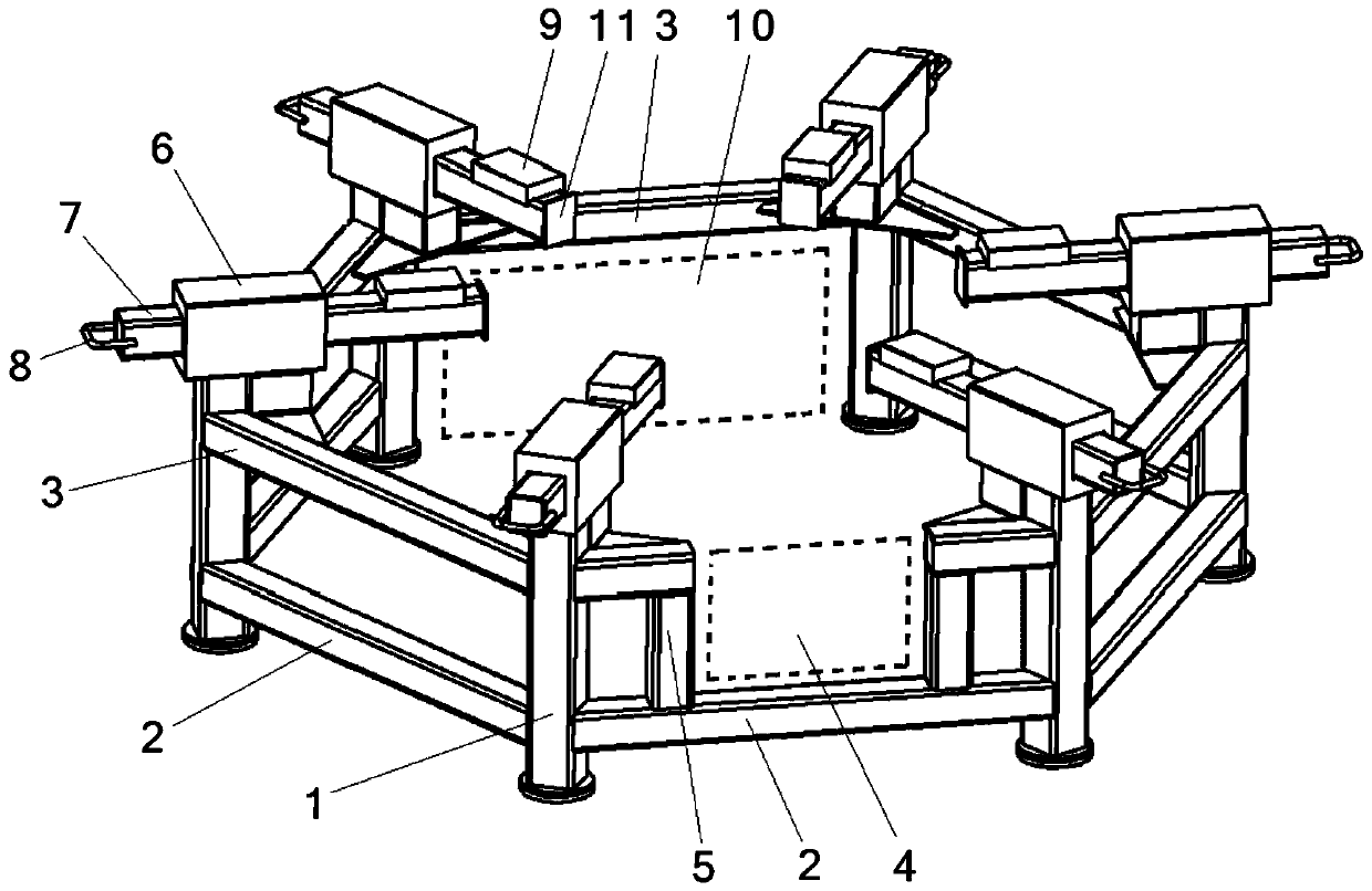
[0012] Such as figure 1 As shown, a large-scale transformer coil placement frame is formed by arranging the six vertices of six legs 1 in a regular hexagon; the two legs 1 on the front are fixedly connected by the lower beam 2 and are on the lower beam 2. A pair of uprights 5 are arranged to enclose the coil heading area 4; the respective two legs 1 of the left front side, left rear side, right front side and right rear side are fixedly connected by the lower cross beam 2 and the upper cross beam 3; the two rear legs 1 is fixedly connected by the upper beam 3 and encloses the inspection entrance 10; each leg 1 is fixed with a telescopic bracket fixing seat 6; the telescopic bracket fixing seat 6 points inward to the center of the regular hexagon; the telescopic bracket A telescopic bracket 7 passes through the fixing seat 6; the outward end of the telescopic bracket 7 is provided with a handle 8, and the upper surface of the inward end is provided with a nylon sheath 9; the six...


PUM


Abstract

The invention relates to a large transformer coil storage rack. The large transformer coil storage rack comprises six supporting legs distributed on the six vertexes of a regular hexagon shape. The two supporting legs on the front side are fixedly connected through a lower cross beam, and a pair of upright columns is arranged on the lower cross beam to form a coil end outlet area; the two supporting legs on the front left side face, the two supporting legs on the rear left side face, the two supporting legs on the front right side face and the two supporting legs on the rear right side face are fixedly connected through lower cross beams and upper cross beams; the two supporting legs on the back side are fixedly connected through an upper cross beam to form an inspection entrance; the supporting legs are fixedly provided with telescopic support fixing bases; telescopic supports are arranged in the telescopic support fixing bases in a penetrating mode; a handle is arranged at the outward end of each telescopic support, and a nylon protective sleeve is arranged on the upper surface at the inward end of each telescopic support. When a coil is detected, a safe, stable and reliable placement position is provided for the coil, and the coil end outlet area can be arranged so that depainting and detection of the end of the coil can be achieved conveniently; the inspection entrance is further arranged so that staff can enter the inspection entrance conveniently to inspect the inside of the coil.

Description

Technical field [0001] The invention relates to the field of transformer manufacturing, in particular to a large transformer coil placement frame. Background technique [0002] When the transformer coil current is large, in order to reduce the eddy current loss, the turns of the coil should be composed of several parallel wires or transposed wires, and the insulation condition between the parallel wires or transposed wires should be good. For example, due to a certain defect, parallel wires or short-circuit points between transposed wires will cause increased transformer loss and local overheating, and even burn the entire coil. After the winding is completed, it is necessary to detect whether the parallel wires or the transposed wires are short-circuited due to the damage of the wire insulation during the winding process. Therefore, the finished coil needs a raised storage rack to facilitate the removal of paint and detection of the coil. The existing coil placement method is ...

Claims


Application Information

Patent Timeline
Patent Type & Authority Patents(China)
IPC IPC(8): H01F41/00G01R31/06
CPCG01R31/72H01F41/00
Inventor 马健花虹朱庆民钮秀荣
Owner WUJIANG TRANSFORMER CO LTD
Why Eureka
Try Eureka