
Combined type material storage rack

A combination and material technology, applied in the direction of transportation, packaging, storage devices, etc., can solve the problems of inconvenient management, high labor intensity, occupying space resources, etc., achieve the effect of convenient storage, improve safety, and eliminate visual blind spots

Active Publication Date: 2016-12-07
ANHUI JIANGHUAI AUTOMOBILE GRP CORP LTD
View PDF5 Cites 0 Cited by
  • Summary
  • Abstract
  • Description
  • Claims
  • Application Information

AI Technical Summary

Problems solved by technology

[0002] The traditional material shelf is a welded or combined fixed structure. Due to the limitation of space position, some partitions of the shelf are located higher than the top of the head, while some partitions are located lower. The storage positions formed by these partitions have visual blind spots. , the space utilization rate is not high, and there are certain potential safety hazards; moreover, these partitions with higher or lower positions are inconvenient to access and require greater labor intensity
[0003] In addition, due to the limitation of human body height, the height of traditional material shelves is limited, and the number of parts storage partitions is limited, so the space utilization rate of the work area is greatly reduced. If a large number of materials and parts need to be stored, a large number of traditional material shelves are required , takes up a lot of space resources, and is not easy to manage

Method used


Image

  • Combined type material storage rack
  • Combined type material storage rack
  • Combined type material storage rack

Examples


Embodiment Construction

[0031] In order to enable those skilled in the art to better understand the technical solution of the present invention, the solution will be further described in detail below in conjunction with specific embodiments.

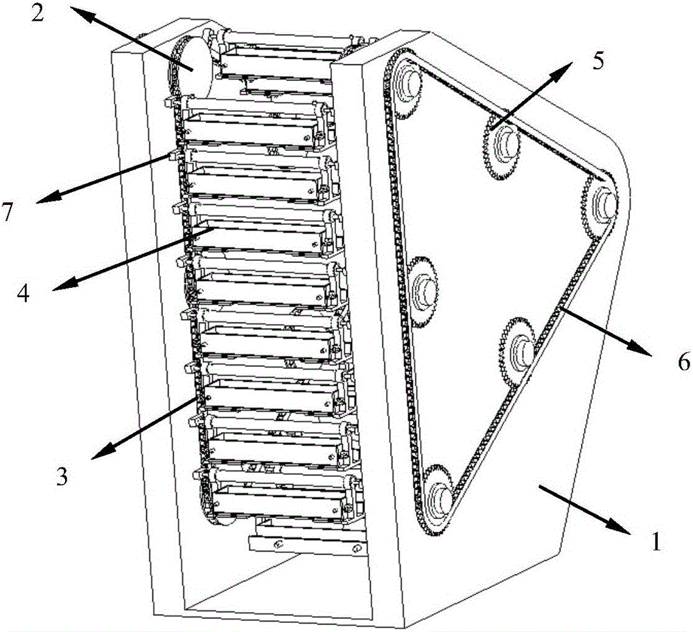
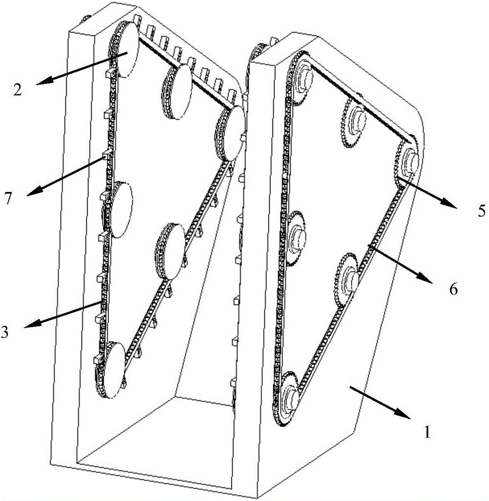
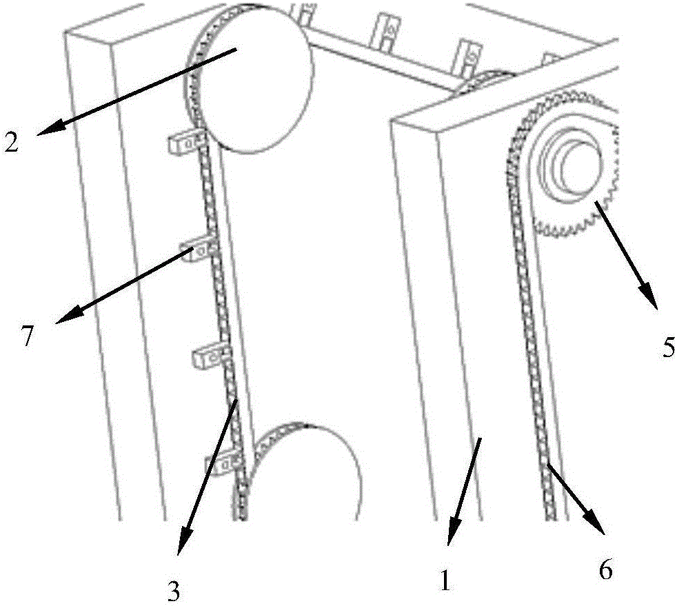
[0032] refer to figure 1 and figure 2 , the embodiment of the present invention provides a combined material shelf, including a shelf body, and the shelf body has two installation plates 1 arranged at a predetermined distance apart. In order to ensure the stability of placement, the two installation plates 1 They can be connected through connecting plates. The inner surfaces of the two mounting plates 1 are provided with a plurality of first sprockets 2, the inner surfaces refer to the opposite surfaces of the two mounting plates 1, wherein the same mounting plate 1 A plurality of the first sprockets 2 are connected through the transmission of the first chain 3, and a plurality of sets of material storage parts 4 are arranged between the two mounting plates ...


PUM


Abstract

The invention relates to the technical field of material storage devices and discloses a combined type material storage rack. The combined type material storage rack comprises a storage rack body. The storage rack body is provided with two installation plates which are spaced at a preset distance. The inner surface of each installation plate is provided with multiple first chain wheels. The multiple first chain wheels on the same installation plate are in transmission connection through a first chain. Multiple groups of material storage portions are arranged between the two installation plates. The two ends of each material storage portion are fixedly connected with portions, adjacent to the material storage portion, of the first chains. The material storage portions are distributed in the circumference direction of the first chains. The outer surface of each installation plate is provided with multiple second chain wheels. The second chain wheels and the first chain wheels on the same installation plate are in one-to-one correspondence. Each first chain wheel and the second chain wheel corresponding to the first chain wheel can synchronously rotate. When the combined type material storage rack works, the multiple second chain wheels on each installation plate rotate sequentially, so that the first chains are driven to move. The combined type material storage rack is high in operation convenience and safety.

Description

technical field [0001] The invention relates to the technical field of material storage devices, in particular to a combined material shelf. Background technique [0002] The traditional material shelf is a welded or combined fixed structure. Due to the limitation of space position, some partitions of the shelf are located higher than the top of the head, while some partitions are located lower. The storage positions formed by these partitions have visual blind spots. , the space utilization rate is not high, and there are certain potential safety hazards; moreover, these partitions with higher or lower positions are inconvenient to access and require greater labor intensity. [0003] In addition, due to the limitation of human body height, the height of traditional material shelves is limited, and the number of parts storage partitions is limited, so the space utilization rate of the work area is greatly reduced. If a large number of materials and parts need to be stored, a...

Claims


Application Information

Patent Timeline
IPC IPC(8): B65G1/04
CPCB65G1/04
Inventor 王森钱多德王善强博士赵帅叶鹏彭镇
Owner ANHUI JIANGHUAI AUTOMOBILE GRP CORP LTD
Learn More