
A device for adjusting the height of the presser foot of a sewing machine

A sewing machine and pressure-adjusting technology, which is applied to sewing machine components, sewing equipment, cloth pressing mechanisms, etc., can solve the problems of costing users, labor, and a lot of time, and achieve the effect of convenient adjustment of the lifting height.

Active Publication Date: 2022-06-28
ZHEJIANG ZOJE SEWING MACHINE
View PDF8 Cites 0 Cited by
  • Summary
  • Abstract
  • Description
  • Claims
  • Application Information

AI Technical Summary

Problems solved by technology

[0004] Although this sewing machine realizes the adjustable lifting height of the presser foot, it also has some shortcomings: the lifting height of the presser foot is to change the connection position between the front end of the ring member and the arc hole by making the pin slide along the arc hole to adjust, but the ring-shaped member is set in the casing of the sewing machine, and the whole casing of the sewing machine needs to be dismantled before adjustment can be made. It must be relatively locked during the swinging process, so when adjusting, not only the casing of the sewing machine must be removed first, but also the pin needs to be loosened, and then the user controls the pin to move along the arc hole to adjust. This causes the adjustment of the lifting height of the entire presser foot to be very cumbersome and laborious, and it will take a lot of time for the user to remove and reinstall the casing of the sewing machine

Method used


Image

  • A device for adjusting the height of the presser foot of a sewing machine
  • A device for adjusting the height of the presser foot of a sewing machine
  • A device for adjusting the height of the presser foot of a sewing machine

Examples


Embodiment Construction

[0038] The following are specific embodiments of the present invention and the accompanying drawings to further describe the technical solutions of the present invention, but the present invention is not limited to these embodiments.

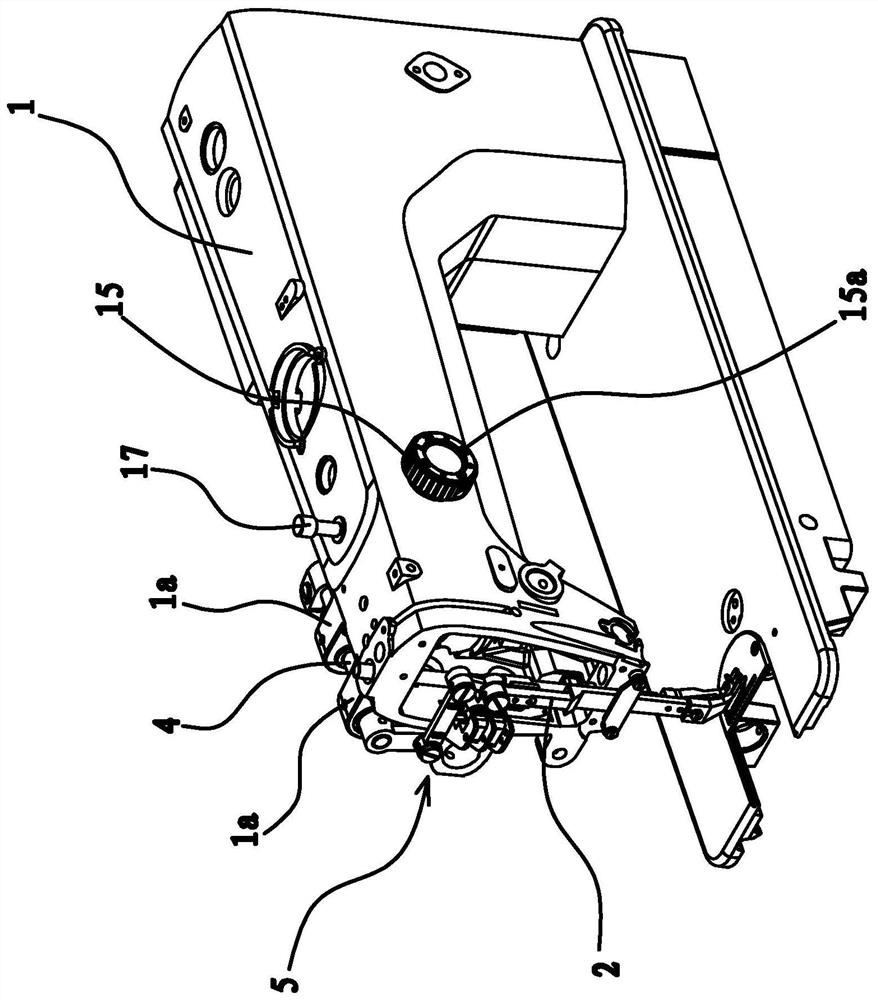
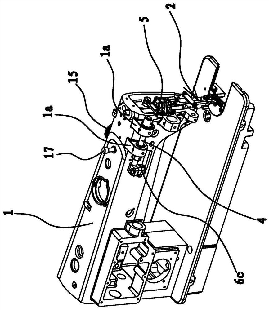
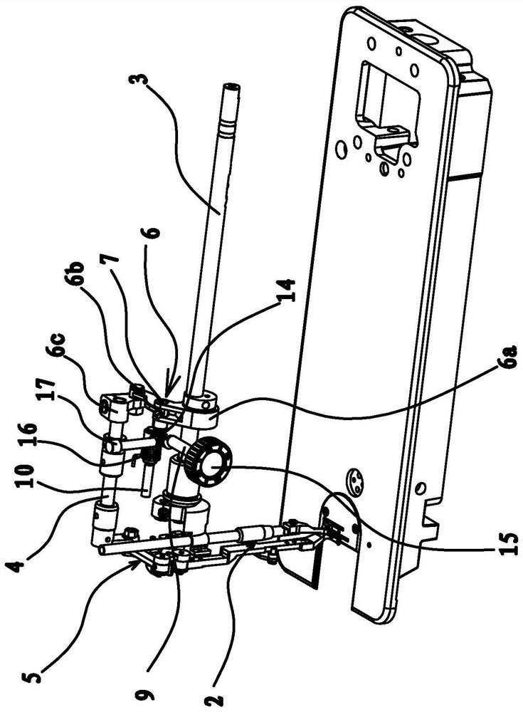
[0039] like figure 1 , figure 2 , image 3 and Figure 4 As shown, a device for adjusting the height of a presser foot of a sewing machine, a presser foot assembly 2 is provided at the head of a casing 1 of the sewing machine, an upper shaft 3 is provided in the body of the casing 1 of the sewing machine along the axial direction, and the sewing machine The outer side of the machine head of the casing 1 has several protruding positioning parts 1a, and a rotatable transmission shaft 4 is passed between each positioning part 1a, and the transmission shaft 4 and the upper shaft 3 are arranged in parallel. A transmission mechanism 5 is arranged between one end of the transmission shaft 4 and the presser foot assembly 2 , and a transmission membe...


PUM


Abstract

The invention provides a device for adjusting the height of a presser foot of a sewing machine, which belongs to the technical field of machinery. It solves the troublesome problem of adjusting the existing device for adjusting the height of the presser foot. It includes an adjustment rod, a connecting pin, a connecting rod 1, a connecting rod 2 arranged parallel to the connecting rod 1, and an elastic member all arranged in the fuselage. One end of the connecting rod 1 and one end of the connecting rod 2 are respectively sleeved on the connecting pin. On the other end of connecting rod 1 there is a protruding limiting part, the outer end of the adjusting rod protrudes out of the fuselage, the inner end of the adjusting rod has an adjusting block, and the adjusting block is located below the end of connecting rod 1 with the limiting part , the transmission part includes a transmission sleeve eccentrically arranged on the upper shaft, a transmission rod and a transmission block fixed on the transmission shaft, a pivot shaft is pierced on the transmission sleeve and one end of the transmission rod is fixed to the pivot shaft, and the other end of the transmission rod One end is fixed with the transmission block, and the other end of the second connecting rod which is socketed with the connecting pin is socketed with the pivot. It has the advantages of more convenient adjustment, time saving and labor saving.

Description

technical field [0001] The invention belongs to the technical field of machinery, and relates to an adjusting device of a sewing machine, in particular to a device for adjusting the height of a presser foot of a sewing machine. Background technique [0002] At present, in order to prevent the fabric from rising with the needle due to friction with the needle and causing interference to the sewing, each industrial sewing machine is equipped with a presser foot assembly. When the needle bar leaves the fabric and rises, the presser foot assembly is used to push the fabric downward Press to prevent the needle from pulling up the fabric, and after the needle is completely lifted from the fabric, the presser foot assembly will rise together with the needle bar. The lifting height of the presser foot assembly in the early industrial sewing machines was a fixed value and could not be adjusted. However, with the continuous improvement of industrial sewing machine technology, there ar...

Claims


Application Information

Patent Timeline
Patent Type & Authority Patents(China)
IPC IPC(8): D05B29/02
CPCD05B29/02
Inventor 鲍增金严海军李辉楼俏军
Owner ZHEJIANG ZOJE SEWING MACHINE
Learn More