Drop weight impact test device for secondary loading

A technology of impact test and secondary loading, which is applied in the direction of measuring devices, fuel testing, material inspection products, etc., can solve the problems of inability to effectively evaluate the stability of explosives, large amount of explosives, and failure to meet the requirements of explosive safety performance evaluation.

Active Publication Date: 2018-10-26
INST OF CHEM MATERIAL CHINA ACADEMY OF ENG PHYSICS
View PDF8 Cites 0 Cited by
  • Summary
  • Abstract
  • Description
  • Claims
  • Application Information

AI Technical Summary

Problems solved by technology

People lack awareness of the safety of explosives under multiple loading-unloading effects, and lack suitable loading methods. The existing explosive impact sensitivity test methods can only achieve single loading, which cannot meet the requirements of explosives in the process of penetrating weapons. Requirements for safety performance evaluation require the establishment of relevant test methods to provide important method support for the design and evaluation of explosives for penetrating weapons
[0003] In the traditional drop weight sensitivity test, the amount of powdered explosive is only 30mg~50mg, and the amount of tablet impact sensitivity is only 50mg~100mg. Charge, the amount of charge is large, the drop weight sensitivity of traditional powder and tablet explosives is difficult to characterize the safety in practical application
The large drop weight impact test method reported in the literature, the weight of the drop weight can reach 400kg, can realize a single impact loading of explosives, and can provide support for the impact safety assessment of explosives, but this method can only achieve one loading, which is different from the penetration The actual stress of explosives in weapons is quite different, especially the stability of explosives damaged by impact cannot be effectively evaluated when they are reloaded

Method used


Image

  • Drop weight impact test device for secondary loading

Examples


Embodiment Construction

[0021] The present invention will be further described in detail below in conjunction with examples, but the embodiments of the present invention are not limited thereto.

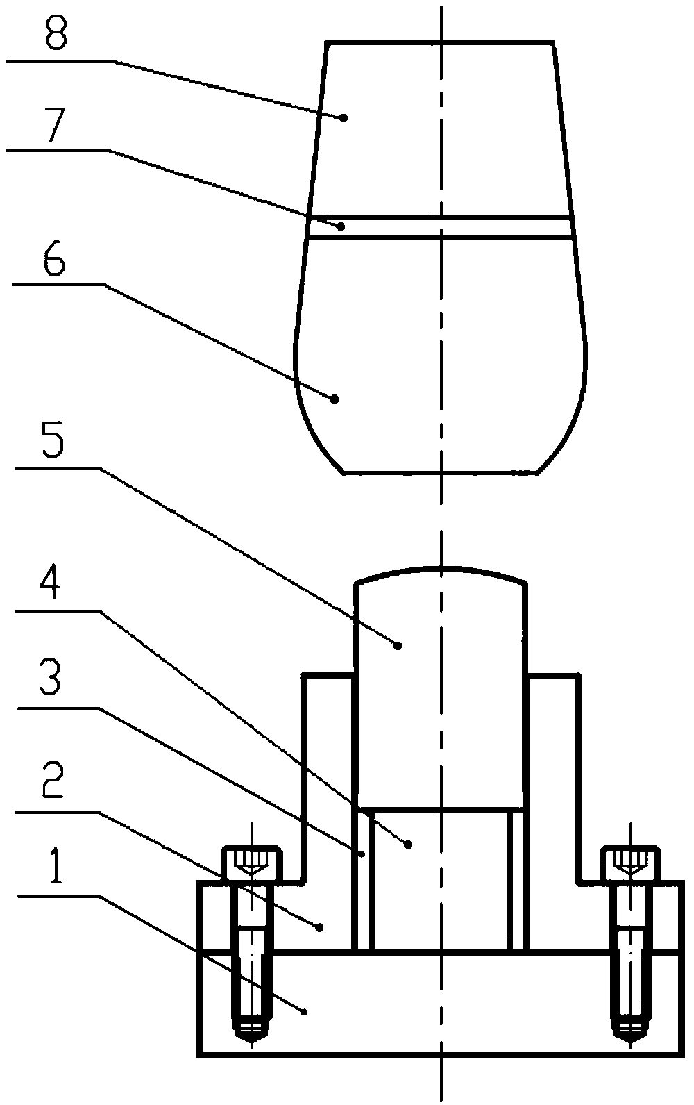
[0022] Such as figure 1 as shown, figure 1 It shows a schematic structural diagram of a drop weight impact test device for realizing secondary loading according to an embodiment of the present invention. A drop weight impact test device for realizing secondary loading includes a base 1, a sample cover 2, An inert ring 3, an explosive cavity 4, a peg 5 and a drop weight, the sample set 2 is arranged on the base 1, the inert ring 3 is set inside the sample set 2, and the lower end of the peg 5 is located In the inert ring 3 and the peg 5 is located above the sample set 2, an explosive cavity 4 for placing explosives is formed between the sample set 2 and the peg 5, and above the peg 5 A drop hammer is set, and the drop hammer is composed of a primary hammer body 6, a buffer layer 7 and a secondary hammer bo...


PUM

PropertyMeasurementUnit
diameteraaaaaaaaaa
heightaaaaaaaaaa
weightaaaaaaaaaa

Abstract

The invention discloses a drop hammer impact test device for realizing second loading. The device comprises a base, a sample sleeve, an inertia ring, an explosive chamber, an impact plunger and a drop hammer, wherein the sample sleeve is arranged on the base; the inertia ring is arranged in the sample sleeve; the lower end of the impact plunger is positioned in the inertia ring, and the impact plunger is positioned above the sample sleeve; the explosive chamber for placing explosives is surrounded by the sample sleeve and the impact plunger; the drop hammer is arranged above the impact plunger and is composed of a primary hammer body, a buffer layer and a secondary hammer body; and the primary hammer body, the buffer layer and the secondary hammer body are sequentially arranged from bottom to top. According to the invention, the explosives can be subjected to second impact loading in a primary test, and impact safety data of the explosives is obtained, so that the safety of the explosives under the action of the second impact loading is well evaluated.

Description

technical field [0001] The invention relates to the technical field of mechanical response and safety evaluation of energetic materials, in particular to a test device for evaluating the safety of energetic materials under secondary loading. Background technique [0002] During the target penetration process of the penetrating weapon, the entire warhead will bear a high overload (up to tens of thousands of g). During the penetration process, due to the multiple reflections of stress waves in the charge, the charge inside the warhead will undergo multiple loading-unloading processes. This process is characterized by multiple high-amplitude (hundreds of MPa) long pulses (milliseconds) loading and unloading. During this process, cracks may be formed inside the explosive, and there are relative movement and friction between the internal interfaces. These phenomena will cause the explosive to ignite during the penetration process, which will bring harsh conditions to the safety ...

Claims


Application Information

Patent Timeline
Patent Type & Authority Patents(China)
IPC IPC(8): G01N33/22
CPCG01N33/227
Inventor 黄谦柴传国薛鹏伊陈红霞
Owner INST OF CHEM MATERIAL CHINA ACADEMY OF ENG PHYSICS
Why Eureka
Try Eureka