Digital bidirectional constant current source

A constant current source, digital technology, applied in the direction of adjusting electrical variables, control/regulating systems, instruments, etc., can solve problems such as system scalability and flexibility limitations, stand-alone operation, and inability to use microcomputer program control.

Active Publication Date: 2016-12-07
JILIN UNIV
View PDF5 Cites 2 Cited by
  • Summary
  • Abstract
  • Description
  • Claims
  • Application Information

AI Technical Summary

Problems solved by technology

[0004] However, the technology disclosed in patent 2015110087701 is entirely based on analog circuits. This circuit has many disadvantages. The function is relatively single, and it can only work on a stand-alone computer. Redesign and production of hardware circuits greatly restrict the scalability and flexibility of the system

Method used


Image

  • Digital bidirectional constant current source
  • Digital bidirectional constant current source
  • Digital bidirectional constant current source

Examples


Embodiment 1

[0041] Embodiment 1 Overall structure of the system

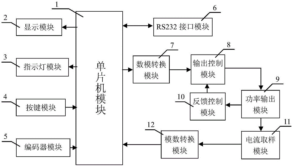
[0042] Such as figure 1 and Figure 14 As shown, the system structure includes MCU module 1, display module 2, indicator light module 3, button module 4, encoder module 5, RS232 interface module 6, digital-to-analog conversion module 7, output control module 8, power output module 9, feedback A control module 10 , a current sampling module 11 , an analog-to-digital conversion module 12 and a front panel 13 .

Embodiment 2

[0043] Embodiment 2 MCU module

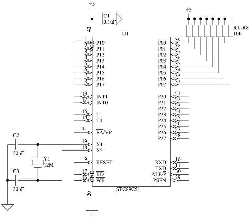
[0044] Such as figure 2 As shown, the structure of the single-chip microcomputer module 1 is that the power supply terminal and the ground terminal of the single-chip microcomputer U1 are connected to +5V power supply and digital ground respectively, the power supply terminal is also connected to the digital ground through the capacitor C1, and the crystal oscillator Y1 is connected between the port X1 and the port X2. Port X1 and port X2 are also connected to digital ground through capacitor C2 and capacitor C3 respectively, and ports P00 to port P07 are respectively connected to +5V power supply through resistors R1 to R8. ), P1 mouth (P10~P17), P2 mouth (P20~P27) are common input / output ports, use P0 mouth in the present invention as the data exchange mouth of single-chip microcomputer and A / D, D / A and display chip, P2 Each pin of the port and P3 port is used as the control terminal to realize the coordinated work of the chips in the contr...

Embodiment 3

[0045] Embodiment 3 display module

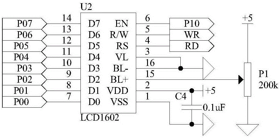
[0046] Such as image 3 As shown, the structure of the display module 2 is that the ports D0-D7 of the display screen U2 are respectively connected to the ports P00-P07 of the single-chip microcomputer U1, and the ports EN, port R / W and port RS of the display screen U2 are connected to the single-chip microcomputer respectively. Port P10, port WR and port RD of U1, port VL and port BL- of display screen U2 are connected to digital ground, port BL+ is connected to the sliding wire end of sliding rheostat W1, port VDD and port VSS are respectively connected to +5V power supply and digital ground, A capacitor C4 is also connected between the port VDD and the port VSS, one end of the sliding rheostat W1 is connected to a +5V power supply, and the other end is connected to a digital ground. The model of the display screen U2 is LCD1602, which is a 16*2 integrated liquid crystal display with 14 pins in total. The port VDD and the port VSS are th...


PUM


Abstract

The invention belongs to the technical field of electronic equipment, and provides a digital bidirectional constant current source. The digital bidirectional constant current source structurally comprises an output control module (8), a power output module (9), a feedback control module (10) and a front panel (13), and is characterized by further structurally comprising a single chip microcomputer module (1), a display module (2), an indicator light module (3), a key module (4), an encoder module (5), an RS232 interface module (6), a digital-to-analog conversion module (7), a current sampling module (11) and an analog-to-digital conversion module (12). The digital bidirectional constant current source is based on control of a single chip microcomputer, and has the advantages of rich function, high convenience in upgrading, high programmable controllability, and the like, and has the function of controlling both analog negative feedback and digital negative feedback, high stability and wide application occasions.

Description

technical field [0001] The invention belongs to the technical field of electronic equipment, in particular to a digital bidirectional constant current source device. Background technique [0002] The constant current source has important applications in many occasions such as optical fiber communication, LED lighting, and laser drive. In some occasions, such as laser drive, the output current stability of the constant current source is very important, and the instability of the output current will cause Affect the life of the laser and the output optical power. Commonly used measures to improve current stability are: 1. Using the nonlinear magnetization principle of magnetic saturation reactor to improve stability; 2. Connecting a large resistance in series in the load circuit (relative to the load resistance); 3. Realizing the current through the negative feedback network Automatic stabilization. Among these schemes, the first scheme is greatly affected by the device itse...

Claims


Application Information

Patent Timeline
Patent Type & Authority Applications(China)
IPC IPC(8): G05F1/575G05F1/573
CPCG05F1/5735G05F1/575
Inventor 汝玉星田小建单江东吴戈高博高福斌李尚安明梁雪刘大恺马春阳
Owner JILIN UNIV
Why Eureka
Try Eureka