Method of layer-by-layer damage analysis on rock

A rock and rock sample technology, applied in the field of layered damage analysis of rocks, can solve the problems of inability to obtain CT average value and inaccurate results, and achieve the effects of narrowing the damage range, simple operation and saving operation time

Active Publication Date: 2016-12-14
安徽省皖江机电设备制造有限公司
View PDF3 Cites 7 Cited by
  • Summary
  • Abstract
  • Description
  • Claims
  • Application Information

AI Technical Summary

Problems solved by technology

[0008] The technical problem to be solved by the present invention is to provide a method for stratified damage analysis of rocks, which can solve the problem that the existing method cannot obtain the CT average value covering all points, and the results are not accurate, and accurately reflect the damage degree of rocks , the degree of damage within the infinitely small damage range can be obtained, and the operation is simple and does not require frequent operations

Method used


Image

  • Method of layer-by-layer damage analysis on rock
  • Method of layer-by-layer damage analysis on rock
  • Method of layer-by-layer damage analysis on rock

Examples


Embodiment 1

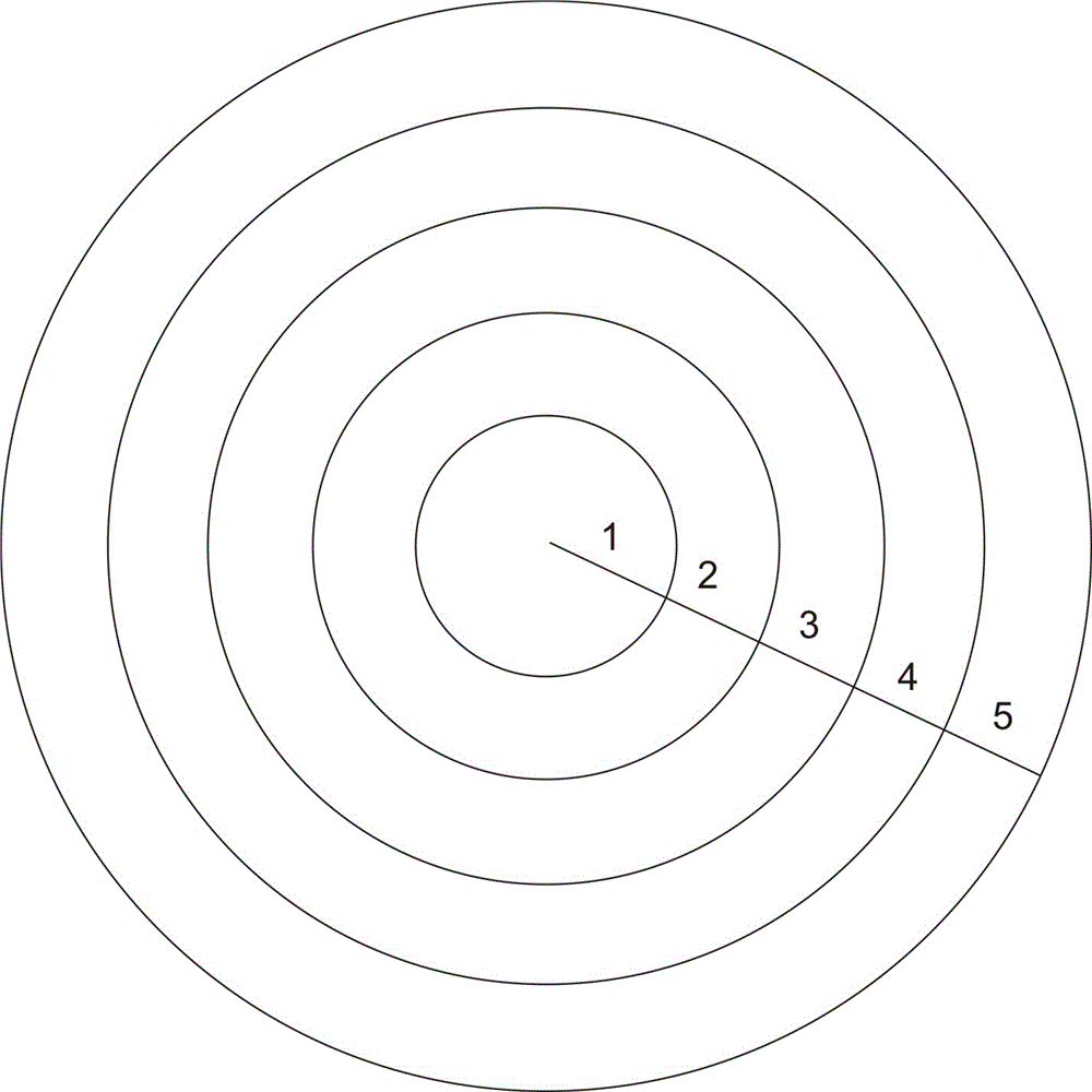
[0034] Step 1: The rock sample is a cylindrical rock sample with a radius of 2.5 cm. Select a cross section on the rock sample, and divide the cross section into regions: starting from the center point of the cross section, divide 5 levels The sample loops with different radii are marked as the first sample ring, the second sample ring, the third sample ring, the fourth sample ring, and the fifth sample ring. The radius difference is 0.5 cm, such as figure 1 Shown

[0035] Step 2: Calculate the CT average CT of each sample ring in the initial state Tave(N) : Perform an initial CT scan on the circle where each sample ring is located, and get the CT value of the circle where each sample ring is located. 1 initial , CT 2 initial , CT 3 initial …CT N initial , Measure the area of ​​the circle where each sample ring is located as S 1 , S 2 , S 3 …S N ,

[0036] CT average value of each ring in the initial state CT Tave(N) initial =(CT N -CT N-1 ) / (S N -S N-1 )

[0037] N=5;

[0038] ...

Embodiment 2

[0053] The method also includes step 5:

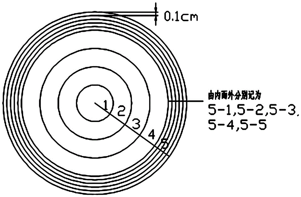
[0054] Step 5: The fifth sample ring where the damage to the rock is mainly concentrated by the freeze-thaw cycle obtained in step 4 is again divided into regions. Starting from the center point of the cross section, the damage concentrated parts are divided into M (M=5) ) The sample loops with equal radius difference are the 5-1 sample ring, the 5-2 sample ring, the 5-3 sample ring, the 5-4 sample ring and the 5-5 sample ring respectively. image 3 As shown, the radius difference is 0.1 cm; and then according to steps 2-4 of the above embodiment 1, the data sorted out is shown in Table 3:

[0055] table 3

[0056]

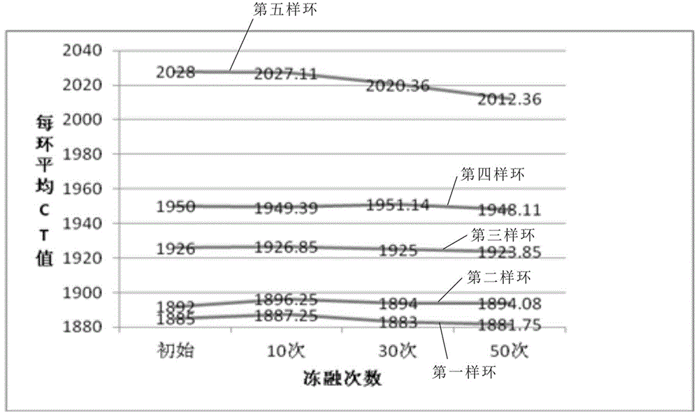
[0057] According to the data in Table 3, the average CT value of each ring-the number of freeze-thaw cycles curve graph, such as Figure 4 Shown from Figure 4 It can be seen that the CT value of sample ring 5-5 has the most obvious change, and the gap ratio has the largest change. Therefore, the damage to the rock caused by the ...

Embodiment 3

[0060] The sample ring can also be designed as a rectangle, and the n sample rings with equal radius difference are divided into a rock sample with a rectangular cross section, such as Figure 5 As shown, the analysis is performed according to the steps of the first and second embodiments above.


PUM


Abstract

The invention relates to a method of a layer-by-layer damage analysis on rock. The method comprises: step one, region division is carried out on a cross section; step two, a CT average value CT Tave (N) of all sample loops in an initial state is calculated; step three, n groups of freezing-thawing cycle tests with different numbers of times are carried out on a rock sample, and a CT average value CT Tave (N) nth group of all sample loops after all groups of freezing-thawing cycle tests is calculated respectively; and step four, data obtained at the step two and the step three are arranged, a damage analysis is carried out the rock, and a concentrated part with rock sample damages caused by the freezing-thawing cycle tests is determined. According to the method, problems that a CT average value covering all points can be not be obtained by the existing method and the result is not accurate can be solved; the damge degree of the rock can be reflected precisely; the damage degree in an infinitely small damage range can be obtained; the operation is simple and frequent operation is avoided.

Description

Technical field [0001] The invention relates to a method for conducting damage analysis on a rock sample, in particular to a method for conducting layered damage analysis on a rock. Background technique [0002] With the deepening of scientific research, most of the current methods for damage analysis of rock samples are CT scans of damaged rock samples, and the degree of damage inside the rock is analyzed by the degree of brightness and CT value of the image after the CT scan. At this stage, there are three main methods for analyzing rocks through CT scanning: [0003] 1. Use the naked eye to contrast the light and dark of the CT image; [0004] A CT scan of a certain layer of the rock. The brighter the figure, the better the rock compactness. The few black dots in the middle indicate that there are local voids. Although this method can be used to visually observe the contrast of the pores inside the rock and roughly draw the law of damage to the rock, it is impossible to perform ...

Claims


Application Information

Patent Timeline
Patent Type & Authority Applications(China)
IPC IPC(8): G06T7/00
CPCG06T7/0004G06T2207/10081G06T2207/30132
Inventor 刘杰雷岚颜媛媛梁佳丽兰钰支永艳
Owner 安徽省皖江机电设备制造有限公司
Why Eureka
Try Eureka