switchgear

A technology of switch devices and contact parts, applied in the direction of electric switches, emergency protection devices, emergency connections, etc., can solve the problem of small operating load, and achieve the effect of increased operating load and large operating load

Active Publication Date: 2018-10-02
ALPS ALPINE CO LTD
View PDF5 Cites 0 Cited by
  • Summary
  • Abstract
  • Description
  • Claims
  • Application Information

AI Technical Summary

Problems solved by technology

[0007] However, since the conductive member of the switch 900 has a structure in which cutouts are formed in a square spiral shape on a flat metal plate to protrude upward or downward, the operational load during operation is relatively small. The problem

Method used


Image

  • switchgear
  • switchgear
  • switchgear

Examples


Embodiment Construction

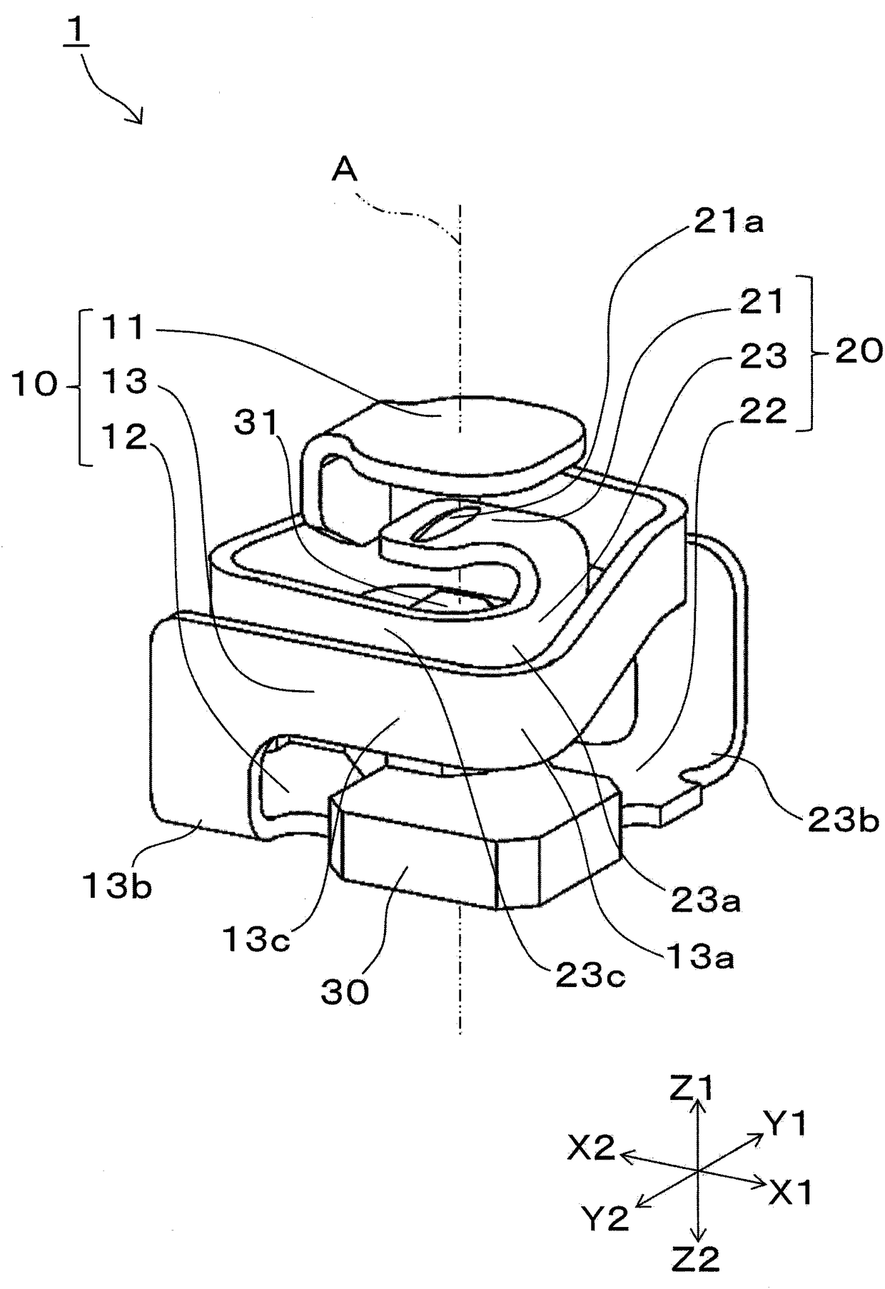
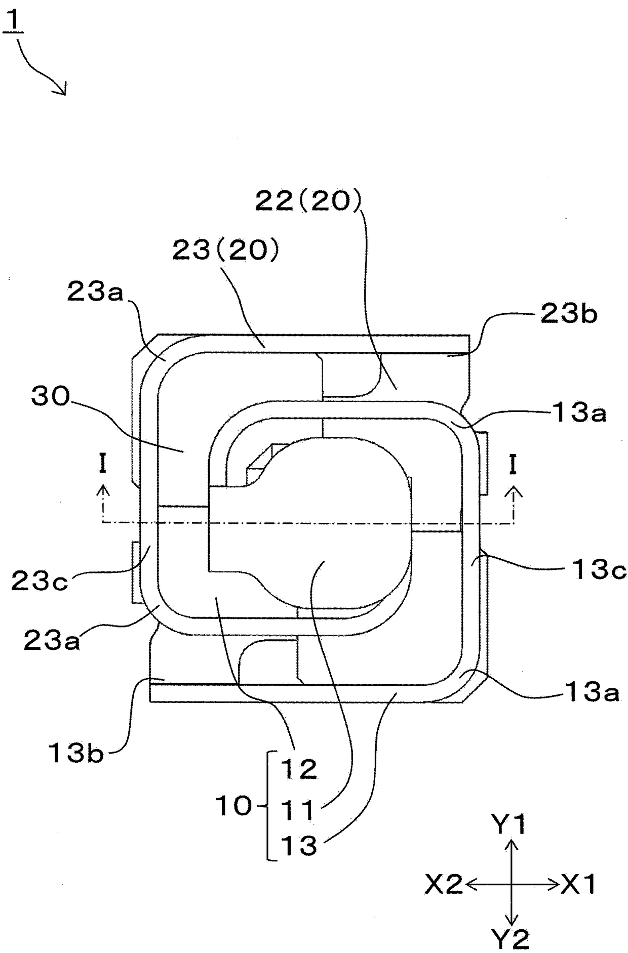
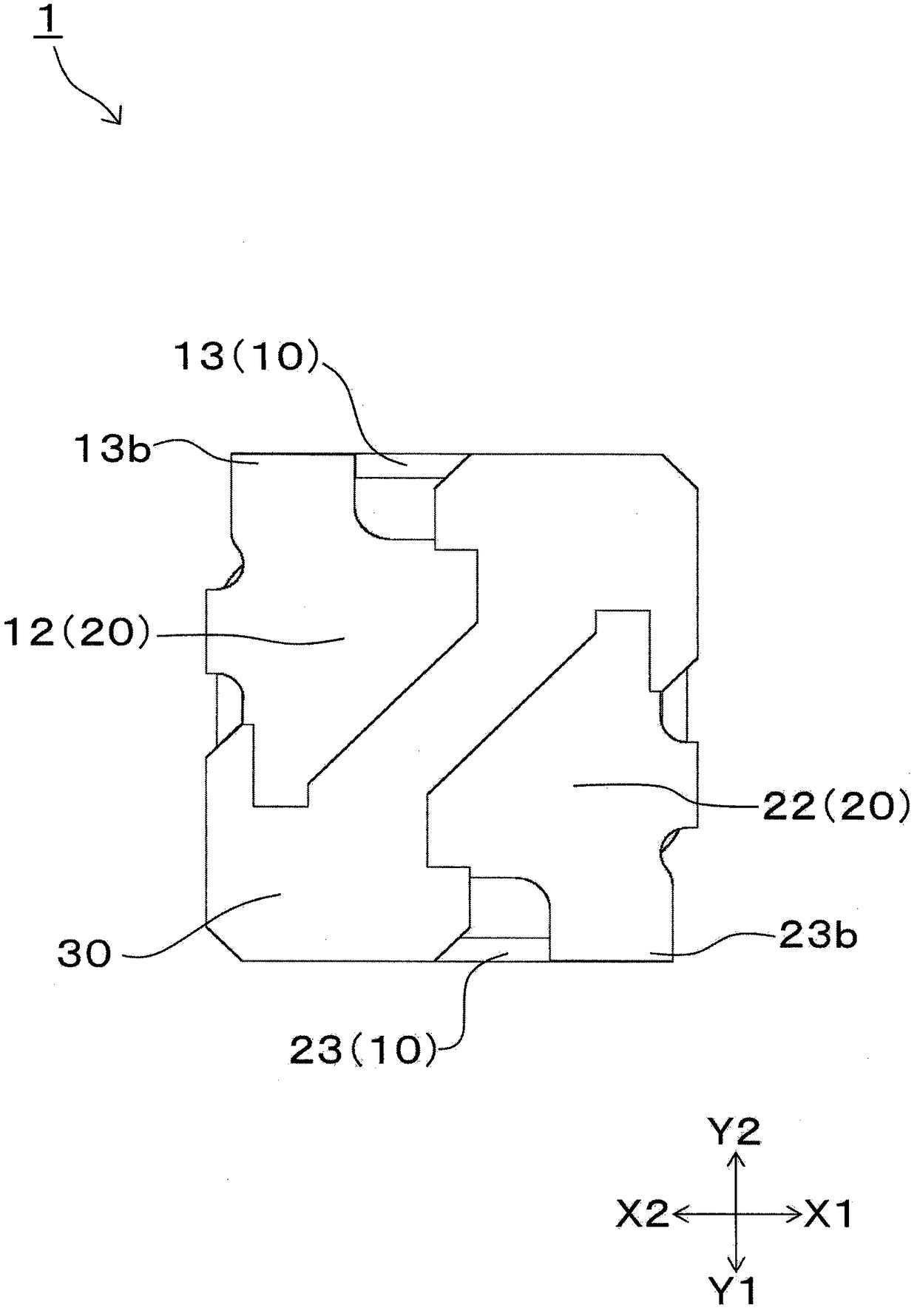
[0054] Below, use Figure 1 to Figure 6 The configuration of the switch device 1 according to the first embodiment of the present invention will be described. figure 1 It is a perspective view showing the switch device 1 according to the first embodiment of the present invention. figure 2 is viewed from above figure 1 The top view of the switching device 1 is shown. image 3 is viewed from below figure 1 Bottom view of the switchgear 1 shown. Figure 4 It is viewed from the Y2 direction figure 1 The side view of the switching device 1 is shown. Figure 5 is viewed from the Z1 direction along the Figure 4 The J-J line shown is a schematic cross-sectional view when the switch device 1 is cut through the first connecting portion 13 . Figure 6 is viewed from the Y2 direction along the figure 2 It is a schematic cross-sectional view of the switch device 1 in the non-pressing operation after the I-I line is shown.

[0055] It should be noted that, in order to explai...


PUM


Abstract

There is a switch with high operation load provided. A first contact (11) and a second contact (21) are separately and oppositely arranged under a non-pressing operation. When the first contact and the second contact are pressed against each other by means of an upper pressing operation, the two contacts are moved downwardly; a first connection part (13) has a first deformation part (13c) that is elastically deformed along with the pressing operation; a second connection part (23) has a second deformation part (23c) that is elastically deformed along with the pressing operation; at least one part of the first deformation part (13c) of the first connection part (13) and at least one part of the second deformation part (23c) of the second connection part (23) have the vertical size which is large than the size in horizontal direction under the section view in the vertical direction.

Description

technical field [0001] The present invention relates to a push-button switch device, and particularly relates to a switch device with a large operation load during operation. Background technique [0002] In recent years, along with the miniaturization of portable devices and the increase in the density of electronic substrates, there are various demands for ultra-small switch devices that can be mounted in extremely small spaces. A switch described in Patent Document 1 is known as a conventional button-type switch device having a small mounting area. [0003] Figure 10 It is an external perspective view of the switch 900. Such as Figure 10 As shown, a conventional switch 900 includes a fixed conductive member 901, a movable conductive member 902, a button 903, and a housing 904 shown by phantom lines. Furthermore, metal wiring is provided which has the external terminal 905 and is arranged so as to always be in contact with the movable conductive member 902 . The fixed...

Claims


Application Information

Patent Timeline
Patent Type & Authority Patents(China)
IPC IPC(8): H01H13/26H01H13/52
CPCH01H13/26H01H13/52H01H2207/03
Inventor 横田纯一郎
Owner ALPS ALPINE CO LTD
Why Eureka
Try Eureka