Projector

A projector and focusing lens technology, applied in the field of projectors, can solve the problem that the human eye cannot fundamentally remove dynamic images, blurred images, and residual vision of the human eye, so as to improve the image quality, reduce the slow response speed, and increase the effect. Effect

Inactive Publication Date: 2016-12-21
TCL CHINA STAR OPTOELECTRONICS TECH CO LTD
View PDF5 Cites 1 Cited by
  • Summary
  • Abstract
  • Description
  • Claims
  • Application Information

AI Technical Summary

Problems solved by technology

However, in recent years, projectors have been used in home theaters. If the projection chips used in home theaters are LCD / LCoS chips, the phenomenon of "smearing" due to dynamic images will be more serious than that of DMD chips, but DMD chips will have a corresponding speed. No matter how fast it is, due to the visual residual phenomenon of the human eye, it is impossible to fundamentally remove the "smear" phenomenon of the dynamic picture only in terms of improving the response speed
[0003] The "smear" phenomenon is mainly caused by two reasons. The first is that the liquid crystal responds for a certain period of time. When switching from the previous image to the next image, there will be an intermediate state of liquid crystal molecules. This intermediate state will The image is blurred; the second reason is that the human eye has a residual visual effect, and the image remains on the retina of the human eye for 10-12ms, so that the first and second images will overlap, resulting in image blur

Method used


Image

  • Projector
  • Projector
  • Projector

Examples


Embodiment Construction

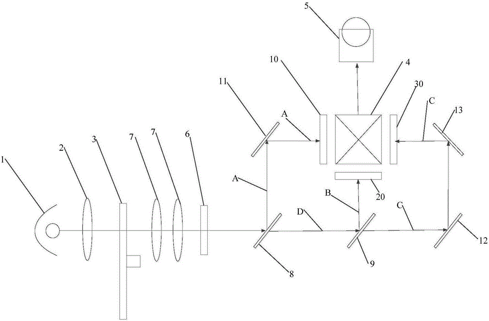
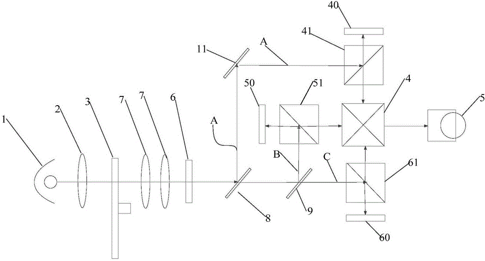
[0039] The details of the present invention can be understood more clearly with reference to the accompanying drawings and the description of specific embodiments of the present invention. However, the specific embodiments of the present invention described here are only for the purpose of explaining the present invention, and should not be construed as limiting the present invention in any way. Under the teaching of the present invention, the skilled person can conceive any possible deformation based on the present invention, which should be considered as belonging to the scope of the present invention, and the present invention will be further described below in conjunction with the accompanying drawings.

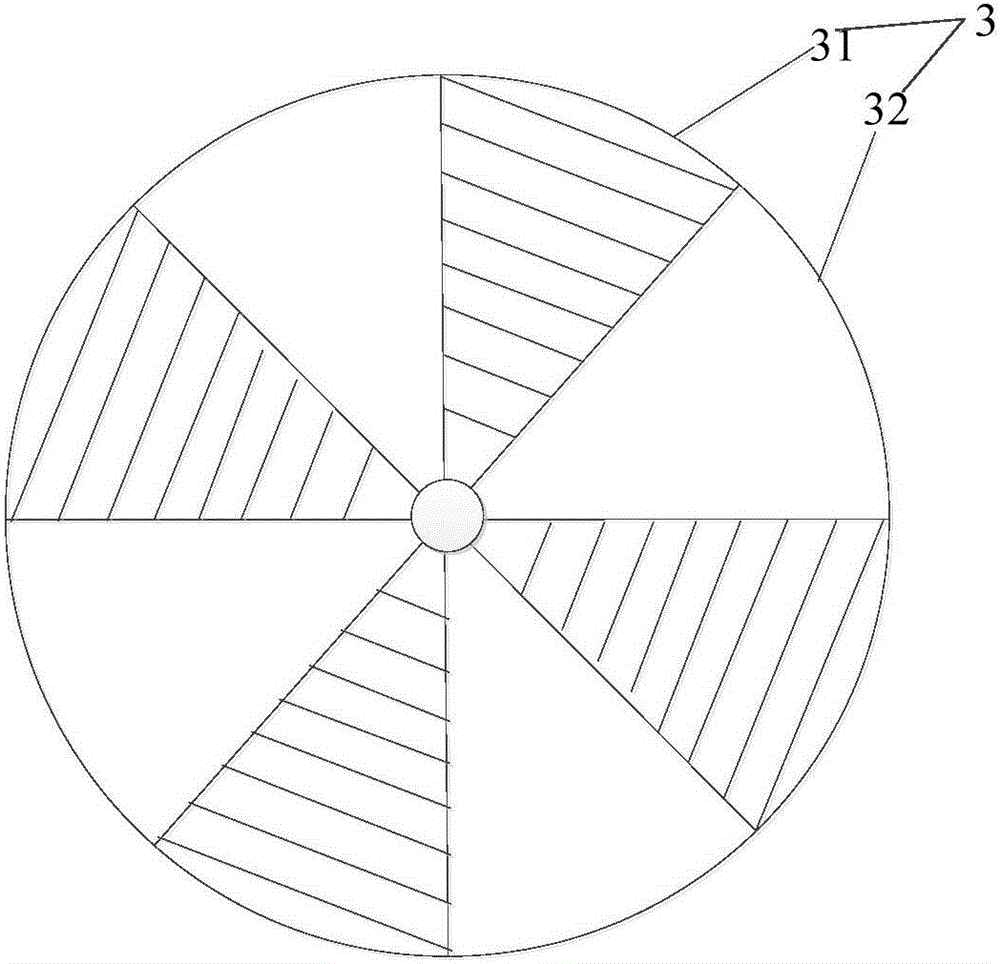
[0040] Figure 1 to Figure 8 They are respectively the schematic diagram (1) of the projector of the present invention, the schematic diagram (2) of the projector, the structural schematic diagram (1) of the switching wheel, the structural schematic diagram (2) of the swi...


PUM


Abstract

The invention discloses a projector, which comprises a light source, a focusing lens arranged at one side of the light source, a switching wheel, a linearly polarized light synthesis assembly, a light separating modulator, a beam combiner and a projection lens, wherein the switching wheel is used for blocking or transmitting light formed by the focusing lens at intervals and is arranged at one side, far away from the light source, of the focusing lens; the time of blocking the light formed by the focusing lens is shorter than or equal to the time of transmitting the light formed by the focusing lens; the linearly polarized light synthesis assembly is used for forming linearly polarized light by the light transmitting through the switching wheel and is arranged at one side, far away from the focusing lens, of the switching wheel; the light separating modulator is used for separating multiple colors of light from the linearly polarized light and modulating the multiple colors of light and is arranged at one side, far away from the switching wheel, of the linearly polarized light synthesis assembly; the beam combiner is used for combining the modulated multiple colors of light; and the projection lens is arranged at one side, far away from the light separating modulator, of the beam combiner. The projector disclosed by the invention can eliminate a ''smearing'' phenomenon, so that the image quality can be improved and the viewing experience effect is improved.

Description

technical field [0001] The invention relates to the technical field of image processing, in particular to a projector. Background technique [0002] Traditional projectors are only used in office situations, and usually only display static images, so that the images will not appear "dragging" of dynamic images caused by the slow response speed of liquid crystals in LCD / LCoS chips and the residual visual phenomenon of the human eye itself. shadow” phenomenon. However, in recent years, projectors have been used in home theaters. If the projection chips used in home theaters are LCD / LCoS chips, the phenomenon of "smearing" due to dynamic images will be more serious than that of DMD chips, but DMD chips will have a corresponding speed. No matter how fast it is, due to the visual residual phenomenon of the human eye, it is impossible to fundamentally eliminate the "smear" phenomenon of the dynamic picture only in terms of improving the response speed. [0003] The "smear" pheno...

Claims


Application Information

Patent Timeline
Patent Type & Authority Applications(China)
IPC IPC(8): G03B21/14
CPCG03B21/14G03B33/08H04N9/3105H04N9/315G03B21/006G03B21/2053G03B21/2073G03B21/208G02B26/04G02B27/149G02B27/286G02B26/02G02B27/102G02B27/14G03B33/12
Inventor 徐向阳
Owner TCL CHINA STAR OPTOELECTRONICS TECH CO LTD
Why Eureka
Try Eureka