Image jitter compensation method and device and storage medium
An image, original image technology, applied in the field of image processing, to solve the effect of image smear
- Summary
- Abstract
- Description
- Claims
- Application Information
AI Technical Summary
Problems solved by technology
Method used
Image
Examples
Embodiment 1
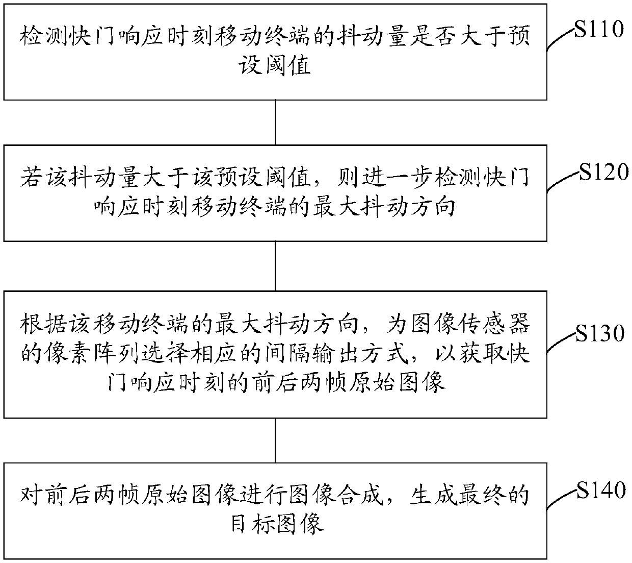
[0023] Such as figure 1 As shown, this embodiment provides a method for image shake compensation, which includes the following steps:
[0024] Step S110: Detect whether the shaking amount of the mobile terminal at the moment of shutter response is greater than a preset threshold.
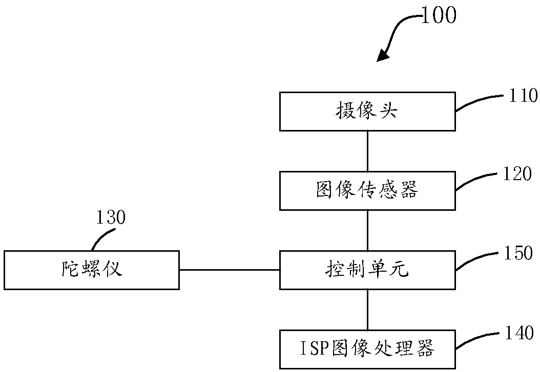
[0025] Specifically, the image shake compensation method of the present invention is mainly based on figure 2 The mobile terminal 100 shown is implemented, and the mobile terminal 100 mainly includes a camera 110 , an image sensor 120 , a gyroscope 130 , an ISP image processor 140 and a control unit 150 .
[0026] Wherein, the camera 110 is mainly used for image acquisition during shooting.
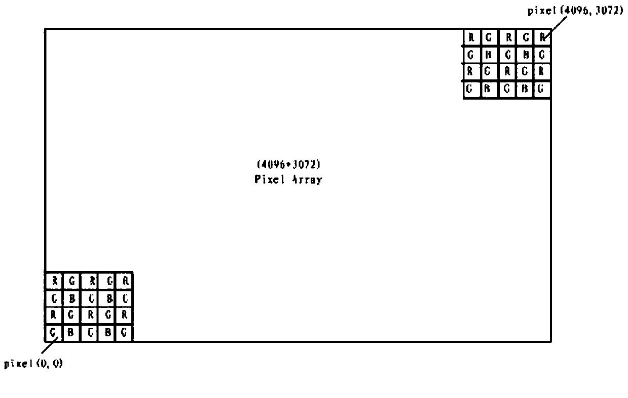
[0027] The image sensor 120 may be a CMOS (ComplementarY Metal OXide Semiconductor, Complementary Metal Oxide Semiconductor) sensor, or a CCD (Charge Coupled Device, Charge Coupled Device) sensor, and the number of pixels of the image sensor 120 may be divided into 5 million, 8 million, 10 million, 12 milli...
Embodiment 2
[0056] Such as Figure 11 As shown, Embodiment 2 of the present invention proposes an image shake compensation device 20, the device 20 includes a memory 21, a processor 22, a program stored in the memory and operable on the processor, and used to implement the processor 21 and the data bus 23 for connection communication between the memory 22, when the program is executed by the processor, to realize the following as figure 1 The specific steps shown:
[0057] Step S110: Detect whether the shaking amount of the mobile terminal at the moment of shutter response is greater than a preset threshold.
[0058] Specifically, the image shake compensation method of the present invention is mainly based on figure 2 The mobile terminal 100 shown is implemented, and the mobile terminal 100 mainly includes a camera 110 , an image sensor 120 , a gyroscope 130 , an ISP image processor 140 and a control unit 150 .
[0059] Wherein, the camera 110 is mainly used for image acquisition duri...
Embodiment 3
[0089] Embodiment 3 of the present invention proposes a computer-readable storage medium, the computer-readable storage medium stores one or more programs, and the one or more programs can be executed by one or more processors to implement the following: figure 1 The specific steps shown:
[0090] Step S110: Detect whether the shaking amount of the mobile terminal at the moment of shutter response is greater than a preset threshold.
[0091] Specifically, the image shake compensation method of the present invention is mainly based on figure 2 The mobile terminal 100 shown is implemented, and the mobile terminal 100 mainly includes a camera 110 , an image sensor 120 , a gyroscope 130 , an ISP image processor 140 and a control unit 150 .
[0092] Wherein, the camera 110 is mainly used for image acquisition during shooting.
[0093] The image sensor 120 may be a CMOS (ComplementarY Metal OXide Semiconductor, Complementary Metal Oxide Semiconductor) sensor, or a CCD (Charge Cou...
PUM
 Abstract
Description
Claims
Application Information
 - R&D
- Intellectual Property
- Life Sciences
- Materials
- Tech Scout
- Unparalleled Data Quality
- Higher Quality Content
- 60% Fewer Hallucinations
Browse by: Latest US Patents, China's latest patents, Technical Efficacy Thesaurus, Application Domain, Technology Topic, Popular Technical Reports.
© 2025 PatSnap. All rights reserved.Legal|Privacy policy|Modern Slavery Act Transparency Statement|Sitemap|About US| Contact US: help@patsnap.com


