Steering gear supporting bushing processing method and supporting bushing structure

A steering gear and bushing technology, applied in steering gears, steering mechanisms, mechanical steering gears, etc., can solve the problems of wear of the support bushing and the surface of the rack, insufficient support of the rack, and reduced support of the rack, etc. Good return performance, avoid abnormal wear and noise, and eliminate the effect of gap changes

Active Publication Date: 2017-01-04
FAWER AUTOMOTIVE PARTS +1
View PDF6 Cites 1 Cited by
  • Summary
  • Abstract
  • Description
  • Claims
  • Application Information

AI Technical Summary

Problems solved by technology

[0004] The invention discloses a processing method of a steering gear support bush and a structure of the support bush to solve the problem that the matching clearance between the support bush and the rack in the prior art is too small, which affects the return performance of the whole vehicle, and causes the support bush and the gear Abnormal wear on the surface of the rack; if the fit clearance is too large, the supporting effect on the rack is reduced; when the radial force of the rack is large, the supporting effect of the rack is insufficient, and the deflection axis of the rack in the bush is prone to appear, which is harmful to the vehicle Steering response can cause issues such as impact

Method used


Image

  • Steering gear supporting bushing processing method and supporting bushing structure
  • Steering gear supporting bushing processing method and supporting bushing structure
  • Steering gear supporting bushing processing method and supporting bushing structure

Examples


Embodiment Construction

[0018] Embodiments of the present invention will be described in detail below in conjunction with the accompanying drawings.

[0019] A method for processing a steering gear support bushing according to the present invention, comprising:

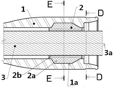
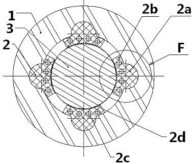
[0020] In the first step, concave grooves 1 a are evenly distributed along the inner hole of the rack housing 1 in the circumferential direction; the number of concave grooves 1 a is 4-9.

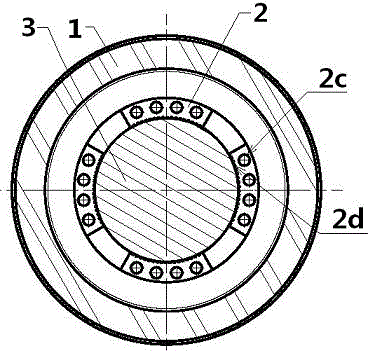
[0021] In the second step, the support pad 2 is injection-molded at the concave groove on the rack housing 1. The injection-molded support pad includes the convex part 2a injected into the concave groove of the rack housing 1, and the injection molding on the rack housing. The annular part 2b of the inner hole of the body 1; the annular part has through holes 2c uniformly distributed in the circumferential direction and serrated protrusions 2d; the convex part 2a and the annular part 2b of the injection-molded support pad are integrated with the rack hous...


PUM


Abstract

The invention discloses a steering gear supporting bushing processing method and a supporting bushing structure. The processing method comprises the following steps: firstly, uniformly forming concave grooves along an inner hole premoulding circumferential direction of a rack shell; and secondly, forming an injection moulding supporting filler block at the concave grooves on the rack shell, wherein the injection moulding supporting filler block comprises convex parts formed in the concave grooves of the rack shell in an injection moulding manner and an annular part formed in a rack shell inner hole in the injection moulding manner; forming through holes and zigzag embossments which are uniformly distributed in the circumferential direction in the injection moulding manner, wherein the zigzag embossments are formed on the circumference surface where the annular part is in contact with a rack; and the zigzag embossments are through along axis direction of the rack, diameter of an inscribed circle of the annular part along the zigzag embossments is smaller than that of the rack, and the supporting filler block formed in the injection moulding manner, the annular part and the rack shell form an integrated structure. Good turning performance of the whole vehicle is guaranteed while fit clearance between the supporting filler block and the rack is small; enough rack supporting is provided in the radial direction; the supporting filler block is formed in the shell in the injection moulding manner, and percent of pass of products is high; and a rack stopping block does not need to be limited in the axial direction.

Description

technical field [0001] The invention belongs to the technical field of automobile steering, and relates to a processing method of a steering gear support bush and a structure of the support bush; it is especially suitable for a rack-and-pinion mechanical steering gear. Background technique [0002] Rack and pinion mechanical steering gear, the sliding part of the rack is supported by the support bushing. [0003] The common structure of the supporting bushing of the automobile steering gear is that the supporting bushing is press-fitted into the inner hole of the rack housing, and the front part of the supporting bushing is equipped with a rack stopper to limit the position of the supporting bushing to prevent the supporting bushing from falling out axially; The bush cooperates with the inner hole of the rack to support the rack. If the matching gap between the supporting bush and the rack is too small, on the one hand, it will affect the alignment performance of the whole ...

Claims


Application Information

Patent Timeline
IPC IPC(8): B29C45/14B62D3/12
CPCB29C45/14B62D3/126
Inventor 贾兵云王泽森
Owner FAWER AUTOMOTIVE PARTS
Why Eureka
Try Eureka