
Air Film Building and Its Internal Ventilation Pipe Structure

A technology of air film buildings and ventilation ducts, which is applied in the direction of buildings, building types, tents/canopies, etc. It can solve the problems of high air velocity requirements, high air velocity, and affecting the activities of people at the bottom, so as to avoid excessive local velocity Effect

Active Publication Date: 2019-01-22
BROADWELL SHENZHEN TECH
View PDF8 Cites 0 Cited by
  • Summary
  • Abstract
  • Description
  • Claims
  • Application Information

AI Technical Summary

Problems solved by technology

Traditional air-film buildings, when inflated directly into the air film, are likely to affect the activities of people at the bottom, causing the air flow rate near the air outlet to be too high and uneven, which cannot meet some specific applications, such as badminton halls for competitions. High air velocity requirements

Method used


Image

  • Air Film Building and Its Internal Ventilation Pipe Structure
  • Air Film Building and Its Internal Ventilation Pipe Structure
  • Air Film Building and Its Internal Ventilation Pipe Structure

Examples


Embodiment Construction

[0026] In order to make the above objects, features and advantages of the present invention more comprehensible, specific implementations of the present invention will be described in detail below in conjunction with the accompanying drawings. In the following description, numerous specific details are set forth in order to provide a thorough understanding of the present invention. However, the present invention can be implemented in many other ways different from those described here, and those skilled in the art can make similar improvements without departing from the connotation of the present invention, so the present invention is not limited by the specific implementations disclosed below.

[0027] It should be noted that when an element is referred to as being “fixed” to another element, it can be directly on the other element or there can also be an intervening element. When an element is referred to as being "connected to" another element, it can be directly connected ...


PUM


Abstract

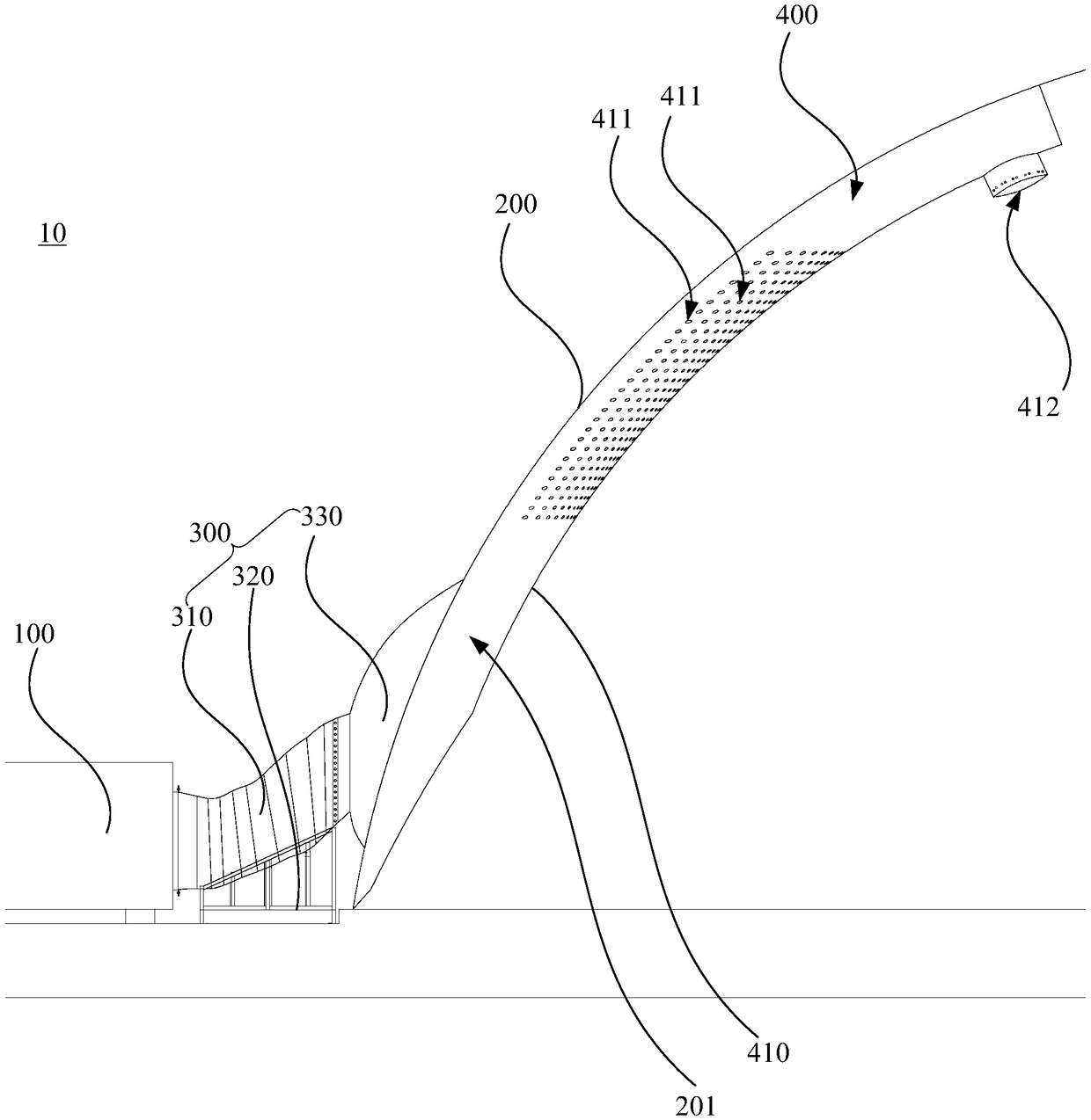
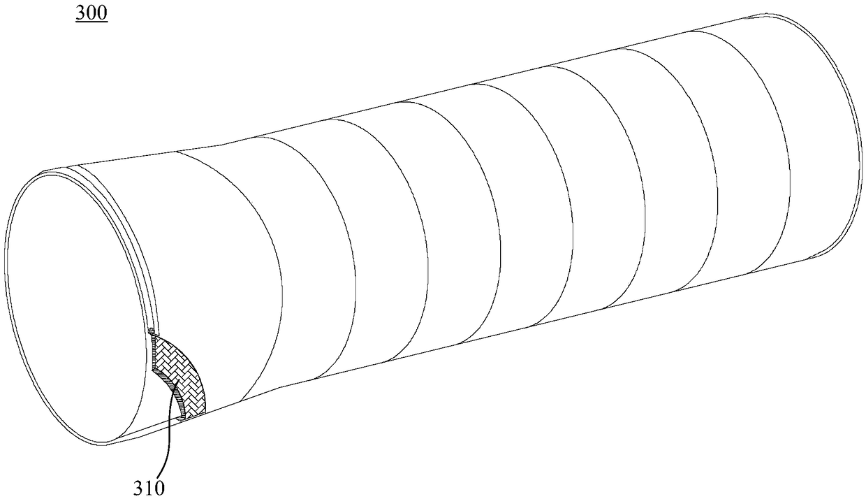
An internal ventilation duct system for an air-supported membrane structure, comprising: a duct wall (410), which is arranged on an inner side of an air-supported membrane main body (200); an internal ventilation duct (201), jointly formed by the duct wall (410) and the air-supported membrane main body (200); an air inlet (210), provided on the air-supported membrane main body (200), air sent by a blower (100) entering the internal ventilation duct (201) by means of said air inlet (210); and a plurality of air outlets (411), arranged at an interval on the duct wall (410) at a position that is away from a bottom portion thereof. Also provided is an air supported membrane structure which comprises the internal ventilation duct structure. The positions of the air outlets of the present structure are relatively high up, which serves to avoid interfering with activities of personnel underneath, and to prevent a local flow rate from becoming too high.

Description

technical field [0001] The invention relates to the technical field of air film buildings, in particular to an air film building and its internal ventilation pipe structure. Background technique [0002] The air film building uses a special architectural membrane material as the shell, and the fan is used to inflate the air film inside, so that the pressure difference between the inside and outside of the air film is formed to maintain a stable shape. Air film buildings are more and more used in all walks of life due to their low cost, fast speed, easy disassembly and assembly, and light weight. [0003] The air film building is to inflate the air film inside through the external ventilation pipe. Traditional air-film buildings, when inflated directly into the air film, are likely to affect the activities of people at the bottom, causing the air flow rate near the air outlet to be too high and uneven, which cannot meet some specific applications, such as badminton halls for...

Claims


Application Information

Patent Timeline
Patent Type & Authority Patents(China)
IPC IPC(8): E04H15/20
CPCE04H15/20E04H2015/206
Inventor 薛飞龙张辉肖龙王秦
Owner BROADWELL SHENZHEN TECH
Learn More