Construction machine

a construction machine and cooling fan technology, applied in machines/engines, stators, liquid fuel engines, etc., can solve the problems of increased suction resistance of cooling fans, low cooling effect of air-cooled coolers, and low cooling effect of inner circumferentials, so as to enhance the cooling efficiency of air-cooled coolers and avoid deterioration of the cooling effect of heat exchangers.

Inactive Publication Date: 2011-01-20
KOBELCO CONSTR MASCH CO LTD
View PDF5 Cites 3 Cited by
  • Summary
  • Abstract
  • Description
  • Claims
  • Application Information

AI Technical Summary

Benefits of technology

[0010]The present invention thus has an object to provide a construction machine, capable of enhancing the cooling efficiency of an air-cooled cooler for EGR without deterioration of the cooling effect of a heat exchanger in spite of the arrangement of the air-cooled cooler for EGR near a cooling fan. Therefore, a construction machine according to the present invention includes: an upper rotating body having an upper frame; a heat exchanger provided on the upper frame, the heat exchanger including an intercooler and a radiator; a cooling fan provided on the upper frame, the cooling fan rotating to generate cooling air for air-cooling the heat exchanger and having properties such that the pressure and flow rate of the cooling air generated by its rotation are relatively low on the inner circumferential side of the fan and high on the outer circumferential side thereof; an EGR line for extracting and recirculating a part of exhaust gas from the exhaust side of the engine to the intake side; and an air-cooled cooler for EGR for cooling the recirculating gas flowing in the EGR line. The air-cooled cooler for EGR is provided in a position on the outer circumferential side of the cooling fan so as to be cooled with the cooling air flowing on the outer circumferential side of the cooling fan.

Problems solved by technology

1) The cooling fan (e.g., axial flow fan) which is generally used for construction machines has properties, as is well known, such that the pressure and flow rate of air flow (cooling air) generated by its rotation are relatively low on the inner circumferential side of the fan and high on the outer circumferential side thereof. Therefore, in the known technique in which the air-cooled cooler is disposed to face the entire surface of the fan, the air-cooled cooler is low in cooling effect on the inner circumferential side of the air-cooled cooler.
2) The longitudinally overlapping arrangement of the heat exchanger and the cooler causes increase in suction resistance of the cooling fan and reduction in cooling air quantity thereof.
The problems 1) and 2) result in not only deterioration of the cooling efficiency of the cooler (exhaust gas) but also deterioration of the cooling effect of the heat exchanger.
This leads to increased cost and makes the equipment layout difficult.

Method used


Image

  • Construction machine
  • Construction machine
  • Construction machine

Examples


first embodiment

1) First Embodiment

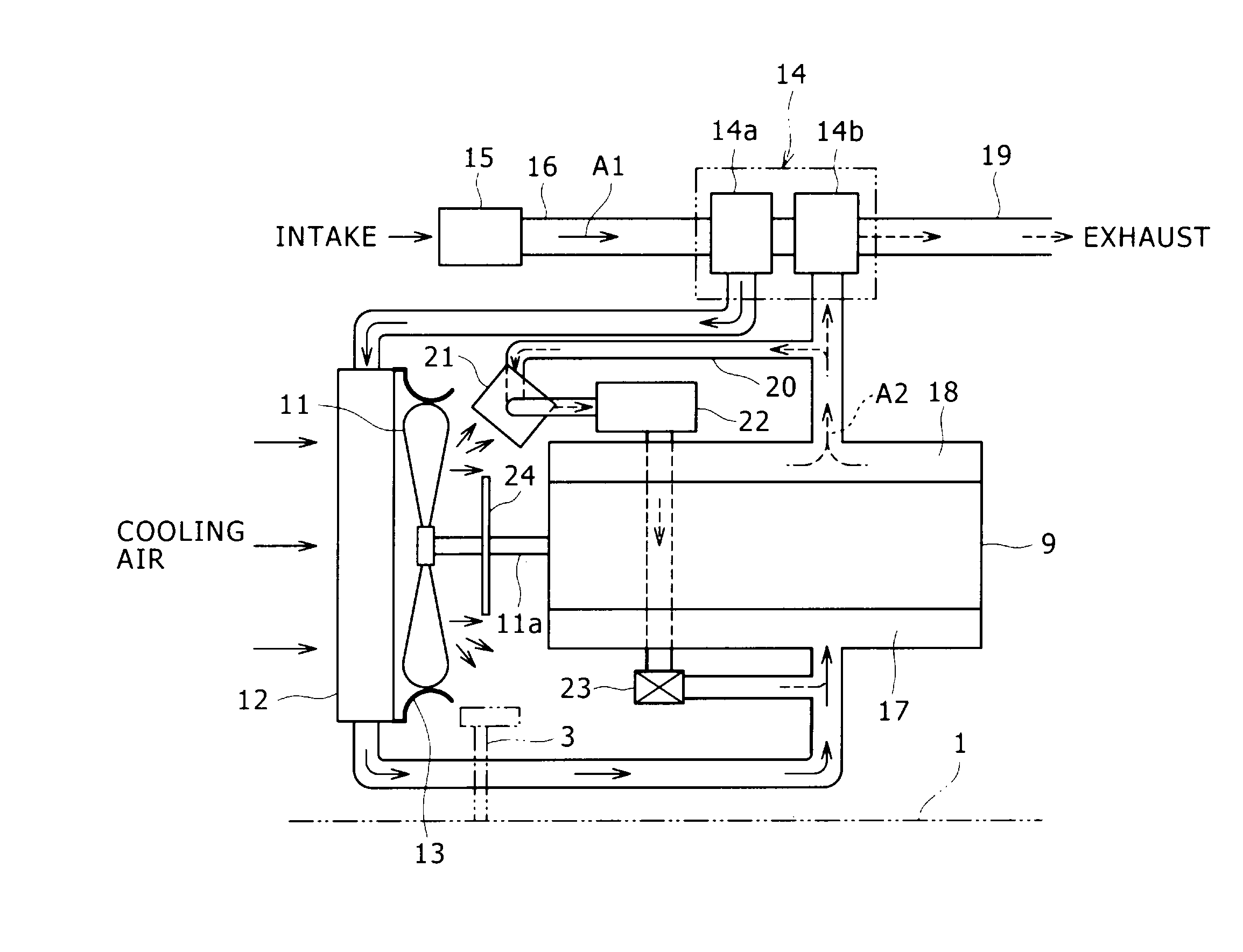
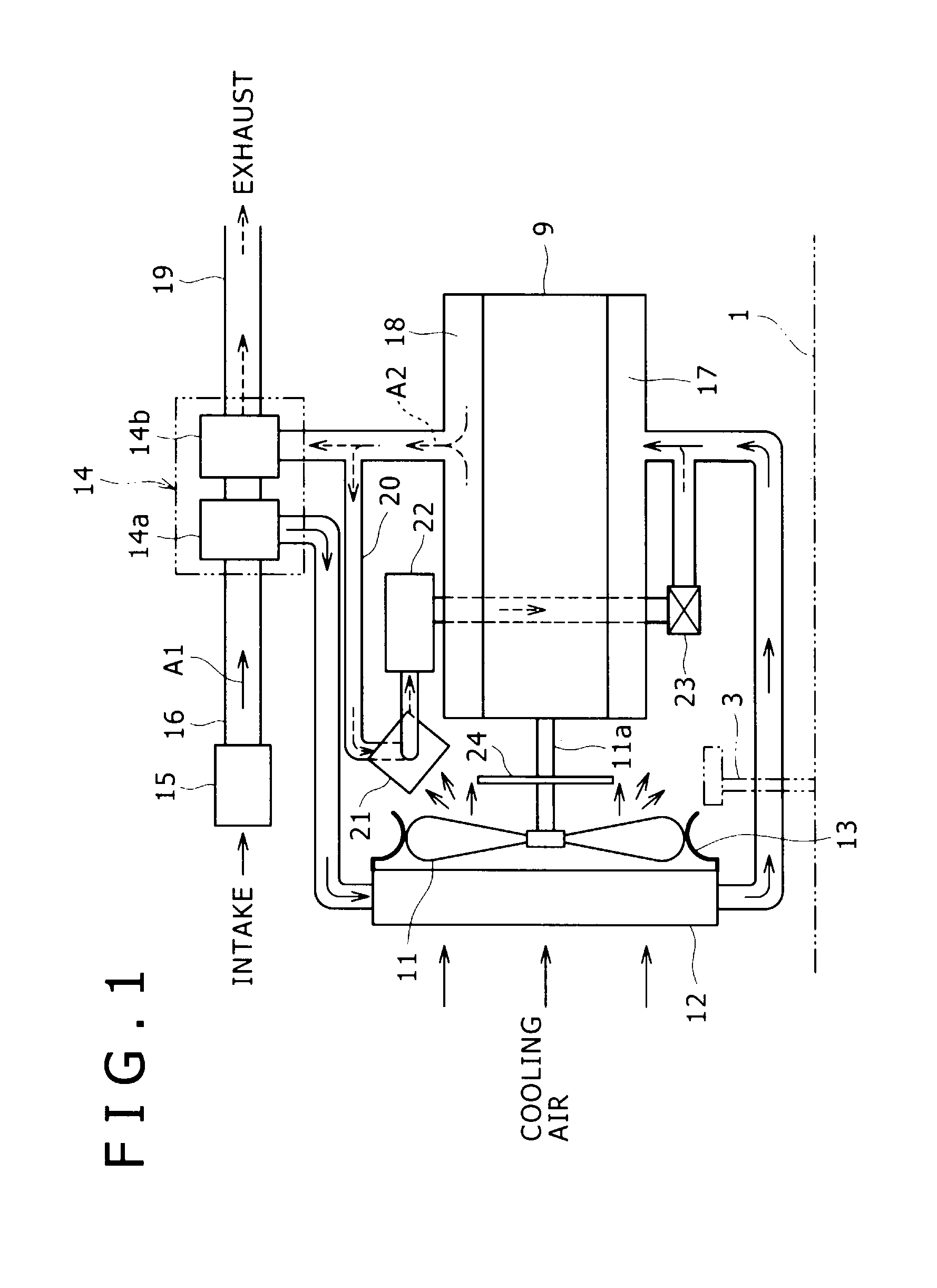
[0023]FIG. 1 shows an intake and exhaust system of an engine including an EGR device, according to the first embodiment. This system includes: a turbo charger 14 provided on the engine 9, an air cleaner 15, an intake pipe 16 and an exhaust pipe 19, an intake manifold 17 and an exhaust manifold 18, an EGR line 20, an air-cooled cooler 21 for EGR (hereinafter often referred simply to as air-cooled cooler), a water-cooled cooler 22 for EGR, and an EGR valve 23.

[0024]The turbo charger 14 includes a compressor 14a and a turbine 14b, and intake air A1 is introduced to the compressor 14a through the air cleaner 15 and the intake pipe 16. The intake air Al is pressurized by the compressor 14a, cooled by the intercooler 12, and then distributed to each cylinder of the engine 9 through the intake manifold 17.

[0025]Exhaust gas A2 is discharged from each cylinder. The exhaust gas A2 is sent to the turbine 14b of the turbo charger 14 through the exhaust manifold 18 to drive th...


PUM


Abstract

The present invention provides a construction machine, capable of enhancing the cooling efficiency of an air-cooled cooler for EGR without deterioration of the cooling effect of a heat exchanger in spite of the arrangement of the air-cooled cooler for EGR near a cooling fan. The construction machine includes: an EGR line 20 for extracting and recirculating a part of exhaust gas from the exhaust side of an engine 9 to the intake side; and an air-cooled cooler 21 for EGR for cooling the recirculating gas flowing in the EGR line 20. The air-cooled cooler 21 for EGR is provided on the outer circumferential side of a cooling fan 11 in a position between the engine 9 and the cooling fan 11 or a position on the downstream side of the cooling fan 11, and cooled with cooling air flowing on the outer circumferential side of the cooling fan 11.

Description

FIELD OF THE INVENTION[0001]The present invention relates to a construction machine such as a hydraulic excavator provided with an EGR device.BACKGROUND ART[0002]Conventionally, as automobile emission control measures, an EGR (Exhaust Gas Recirculation) device for reducing NOx (nitrogen oxide) or PM (particulate matter) by extracting and recirculating a part of exhaust gas to the intake side to thereby reduce the combustion temperature is used, and adoption of the same device is requested also for construction machines such as a hydraulic excavator.[0003]This EGR device requires cooling of extremely high-temperature exhaust gas to a temperature suitable for combustion of an engine, or the like. As this cooling technique, a technique shown in Patent Literature 1 is known. In this known technique, exhaust gas extracted from the exhaust side to an EGR line (exhaust gas recirculation line) is cooled by a water-cooled cooler for EGR using cooling water of a radiator and an air-cooled coo...

Claims


Application Information

Patent Timeline
Patent Type & Authority Applications(United States)
IPC IPC(8): F02M25/07F04D29/52
CPCF01P5/06F01P2060/02F02B29/04Y02T10/121F02M25/073F02M25/0731F02M25/0732F02M25/0707F02M26/05F02M26/24F02M26/27F02M26/28
Inventor IKEDA, TAISUKEYOKOTA, JUMPEI
Owner KOBELCO CONSTR MASCH CO LTD
Why Eureka
Try Eureka