A smart watch nfc antenna device and smart watch

A smart watch and antenna device technology, applied in the wearable field, can solve problems such as signal interference, limited area, and inability to effectively radiate signals, and achieve the effects of reducing impact and increasing distance

Active Publication Date: 2019-01-08
QINGDAO HISENSE MOBILE COMM TECH CO LTD
View PDF6 Cites 0 Cited by
  • Summary
  • Abstract
  • Description
  • Claims
  • Application Information

AI Technical Summary

Problems solved by technology

[0004] However, due to the limited area of ​​the watch case side wall 102, if the surface area of ​​the NFC antenna is required to exceed the set threshold, the distance between the NFC antenna 5 and the main antenna 3 and the auxiliary antenna 4 will be too close, further affecting the main antenna 3 and the auxiliary antenna 4. The signal of the auxiliary antenna 4 causes interference, resulting in a reduction in the radiation performance of the main antenna 3 and the auxiliary antenna 4; in addition, if the NFC antenna 5 is arranged under the screen of the dial 101, the blocking effect of the dial 101 will seriously weaken the radiation performance of the NFC antenna 5 ; Simultaneously, because NFC antenna 5 has suppressing action to the signal that main antenna 3 and auxiliary antenna 4 produce, cause the signal that main antenna 3 and auxiliary antenna 4 produce can't effectively radiate, thereby make the radiation performance of main antenna 3 and auxiliary antenna 4 decline

Method used


Image

  • A smart watch nfc antenna device and smart watch
  • A smart watch nfc antenna device and smart watch
  • A smart watch nfc antenna device and smart watch

Examples


Embodiment 1

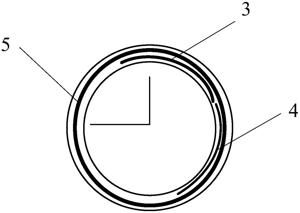
[0051] see image 3 , image 3 It is a schematic structural diagram of an NFC antenna device for a smart watch provided by an embodiment of the present invention.

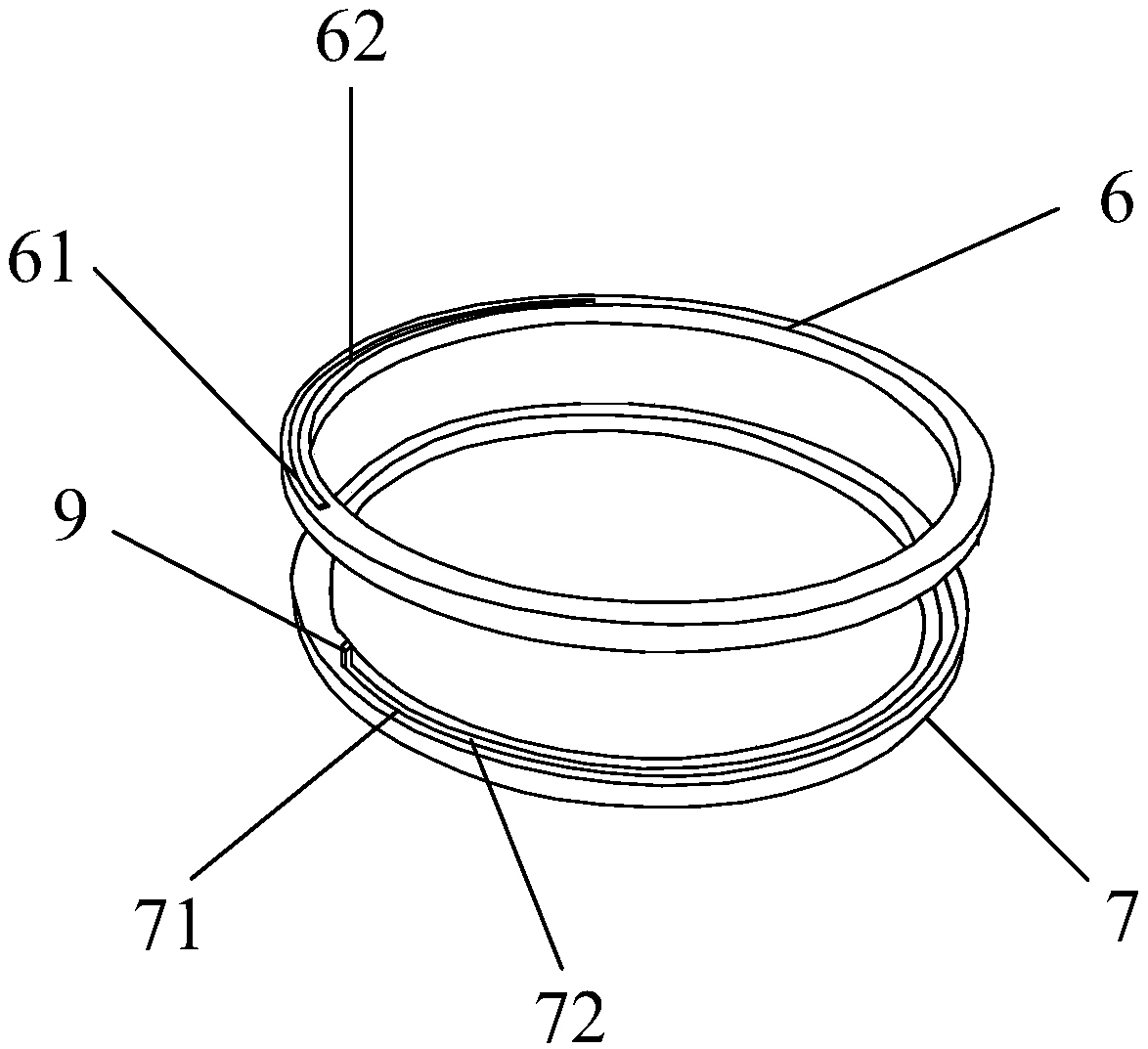
[0052] Such as image 3 As shown, the smart watch NFC antenna device includes a rotating ring 6 and a fixed ring 7, the rotating ring 6 and the fixed ring 7 have the same diameter, and are arranged symmetrically up and down. In specific implementation, the rotating ring 6 is located at the fixed ring 7 above, or the rotating ring 6 can be positioned at the below of the fixed ring 7, the rotating ring 6 can rotate relative to the fixed ring 7, and when rotating, the rotating ring 6 rotates around the center of the ring itself.

[0053] Both the rotating ring 6 and the fixed ring 7 are arranged as a ring body with a frame structure, a first groove 61 is arranged on the frame structure of the rotating ring 6, and a first NFC sub-antenna is arranged in the first groove 61 62. Similarly, a second groove 71 is arrange...

Embodiment 2

[0066] The embodiment of the present invention also provides another smart watch NFC antenna device, see Figure 6 , Figure 6 The antenna device provided in includes a rotating ring 6, a fixed ring 7, and at least one annular slide rail 8.

[0067] The ring slide rail 8 is arranged between the rotating ring 6 and the fixed ring 7, and the ring slide rail 8 has the same diameter as the rotating ring 6 and the fixed ring 7, and is arranged symmetrically with the rotating ring 6 and the fixed ring 7 respectively. . The structures of the rotating ring 6 and the fixed ring 7 are the same as those in the first embodiment, and will not be repeated here. An annular chute is provided on the annular slide rail 8 , and the annular chute is configured as a transparent structure. A third NFC sub-antenna 82 is arranged on the annular chute, and the third NFC sub-antenna 82 can slide in the annular groove 81 .

[0068] The first NFC sub-antenna 62 in the first groove 61 of the rotating r...

Embodiment 3

[0076] The smart watch NFC antenna device provided by the embodiment of the present invention can also be set as Figure 8 The structure shown realizes the automatic rotation of the rotating ring 6 . Such as Figure 8 As shown, the smart watch NFC antenna device also includes a drive assembly 10 and a gear 11 , and internal teeth meshing with the gear 11 are provided on the inner wall of the rotating ring 6 . The output shaft of the drive assembly 10 is connected to the rotation shaft of the gear 11. When the drive assembly 10 is energized and rotated, the gear 11 is driven to rotate, and the gear 11 meshes with the internal teeth on the inner wall of the rotating ring 6, so the gear 11 will drive the rotating ring 6 to rotate , thereby realizing the automatic rotation of the rotating ring 6.

[0077] The driving assembly 10 includes an electric small motor, one end of the electric small motor is electrically connected to the power supply assembly, the other end is provided ...


PUM


Abstract

The invention relates to a smart watch NFC antenna device and a smart watch. The smart watch NFC antenna device comprises a rotating ring and a fixed ring having the same diameter and arranged symmetrically. A first groove is arranged on the rotating ring. A first NFC sub-antenna is fixed in the groove. A second groove is disposed on the fixed ring. A second NFC sub-antenna is fixed in the second groove. The first NFC sub-antenna and the second NFC sub-antenna rotate relatively. Both ends of each sub-antenna are provided with conductive contacts. The conductive contact at one end of the first NFC sub-antenna is located in the second groove and slides along the second groove. The conductive contact at one end of the second NFC sub-antenna is located in the first groove. The surface of each sub-antenna is an insulating surface. The smart watch NFC antenna device unfolds and folds the NFC antennas therein so as to increase the distance between the main sub-antenna and the NFC antennas and reduce the influence of the NFC antennas on the main and auxiliary antenna lines.

Description

technical field [0001] The invention relates to the field of wearable technology, in particular to a smart watch NFC antenna device and a smart watch. Background technique [0002] Smart watches are currently widely used smart wearable devices. In addition to traditional watch functions, they also have some functions of smart phones, such as mobile communication, wireless Internet access and short-range wireless communication. When a smart watch realizes some functions of a smart phone, it needs to set some functional components of the smart phone in a space that is greatly reduced in size compared with the smart phone, for example, the main antenna (2G / 3G / 4G antenna) for receiving and sending signals , secondary antenna (BT / WIFI / GPS antenna) and NFC (Near Field Communication, short-range wireless communication) antenna, etc. [0003] exist figure 1 Among them, the smart watch mainly includes a watch body 1 and a strap 2 , and the watch body 1 includes a dial 101 and a cas...

Claims


Application Information

Patent Timeline
Patent Type & Authority Patents(China)
IPC IPC(8): H01Q1/24H01Q1/22H01Q7/00H01Q7/02H01Q21/00G04R60/10
CPCG04R60/10H01Q1/22H01Q1/24H01Q1/242H01Q7/00H01Q7/02H01Q21/00
Inventor 隋晓东胡罡罡
Owner QINGDAO HISENSE MOBILE COMM TECH CO LTD
Why Eureka
Try Eureka