Active triggering device matched with trigger vacuum switch

A vacuum switch and triggering device technology, applied in electronic switches, electrical components, pulse technology, etc., can solve the problem that the triggering vacuum switch cannot be 100% reliable conduction.

Active Publication Date: 2017-01-04
HUAZHONG UNIV OF SCI & TECH
View PDF3 Cites 5 Cited by
  • Summary
  • Abstract
  • Description
  • Claims
  • Application Information

AI Technical Summary

Problems solved by technology

[0004] Aiming at the defects of the prior art, the purpose of the present invention is to provide an active trigger device used in conjunction with the trigger vacuum switch, aiming to solve the problem that the trigger vacuum switch cannot be 100% reliable in conduction under positive polarity conditions

Method used


Image

  • Active triggering device matched with trigger vacuum switch
  • Active triggering device matched with trigger vacuum switch
  • Active triggering device matched with trigger vacuum switch

Examples


Embodiment Construction

[0017] In order to make the object, technical solution and advantages of the present invention clearer, the present invention will be further described in detail below in conjunction with the accompanying drawings and embodiments. It should be understood that the specific embodiments described here are only used to explain the present invention, not to limit the present invention.

[0018] In order to further illustrate the active trigger device used in conjunction with the trigger vacuum switch provided by the embodiment of the present invention, it is now described in detail in conjunction with the drawings and specific examples as follows:

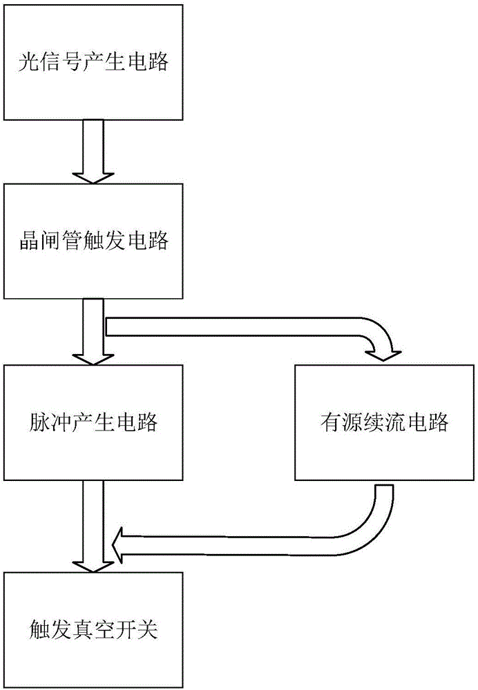
[0019] figure 1 It shows the functional block diagram of the active trigger device used in conjunction with the trigger vacuum switch provided by the embodiment of the present invention. For the convenience of description, only the parts related to the embodiment of the present invention are shown, and the details are as follows:

[00...


PUM


Abstract

The invention discloses an active triggering device matched with a trigger vacuum switch. The active triggering device matched with the trigger vacuum switch comprises an optical signal producing circuit, a thyristor triggering circuit, a pulse generating circuit and an active follow current circuit. The input terminal of the thyristor triggering circuit is connected to the output terminal of the optical signal producing circuit. The thyristor triggering circuit respectively outputs a first pulse signal and a second pulse signal successively. The input terminal of the pulse generating circuit and the input terminal of the active follow current circuit are connected to the output terminal of the thyristor triggering circuit. The output terminal of the pulse generating circuit and the output terminal of the active follow current circuit are used for connecting the input terminal of the trigger vacuum switch. The pulse generating circuit is used for, according to the second pulse signal, outputting a second triggering signal and controlling the trigger vacuum switch to trigger the surface follow current. The trigger voltage is up to 15-20 kV, the trigger current is up to 680 A, and the volume of the trigger device is small.

Description

technical field [0001] The invention belongs to the field of high-power pulse technology, and more specifically relates to an active trigger device used in conjunction with a trigger vacuum switch. Background technique [0002] The trigger vacuum switch is a new type of device that combines vacuum switch technology and three-electrode spark technology, and has been applied in high-power pulse systems. There are two trigger methods for trigger vacuum switches: laser trigger and pulse trigger. The difference is that the former uses laser irradiation to generate initial plasma, and the pulse trigger is to generate initial plasma along the surface through breakdown. For the trigger source that triggers the vacuum switch, its main characteristics are characterized by two quantities: trigger voltage and trigger current. [0003] The following technical problems exist in the work of the trigger vacuum switch: (1) When the trigger vacuum switch is used in the power system, because ...

Claims


Application Information

Patent Timeline
Patent Type & Authority Applications(China)
IPC IPC(8): H03K17/04H03K17/72
CPCH03K17/0403H03K17/72
Inventor 戴玲张钦张凯伦向凌峰
Owner HUAZHONG UNIV OF SCI & TECH
Why Eureka
Try Eureka