A vibrating table device for testing the dynamic characteristics of ring-shaped damping parts

A technology for testing vibration and dynamic characteristics, applied in the mechanical field, can solve the problems of poor universality of the test device, frequent replacement of the test shaft, affecting the accuracy of the test results, etc., and achieve the effects of precise positioning, good compression effect, and convenient installation.

Inactive Publication Date: 2018-11-09
BEIJING WUZI UNIVERSITY
View PDF8 Cites 0 Cited by
  • Summary
  • Abstract
  • Description
  • Claims
  • Application Information

AI Technical Summary

Problems solved by technology

[0004] Therefore, the existing vibrating table device for testing the dynamic characteristics of annular damping parts has some defects: 1) The test device has poor versatility. The test requires frequent replacement of the test shaft; 2) The axial position of the annular damping part cannot be positioned, and the test of the axial dynamic characteristics of the annular damping part cannot be completed; 3) The test device does not have a calibration function, and the test shaft cannot be guaranteed during repeated installation and disassembly. The test direction of the sensor is consistent with the vibration direction of the vibration table, which affects the accuracy of the test results; 4) The test device cannot complete the test of the influence of temperature on the dynamic characteristics of the damping part

Method used


Image

  • A vibrating table device for testing the dynamic characteristics of ring-shaped damping parts
  • A vibrating table device for testing the dynamic characteristics of ring-shaped damping parts
  • A vibrating table device for testing the dynamic characteristics of ring-shaped damping parts

Examples


Embodiment Construction

[0039] The structure and working process of the present invention will be described in detail below in conjunction with the accompanying drawings.

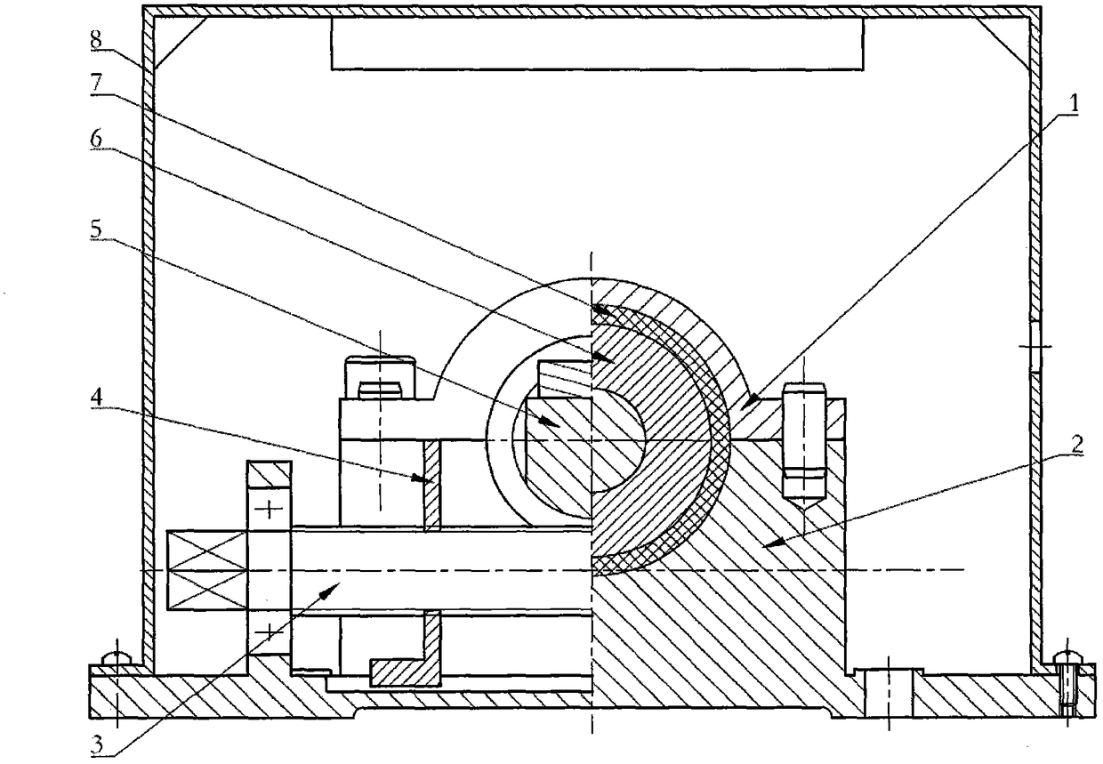
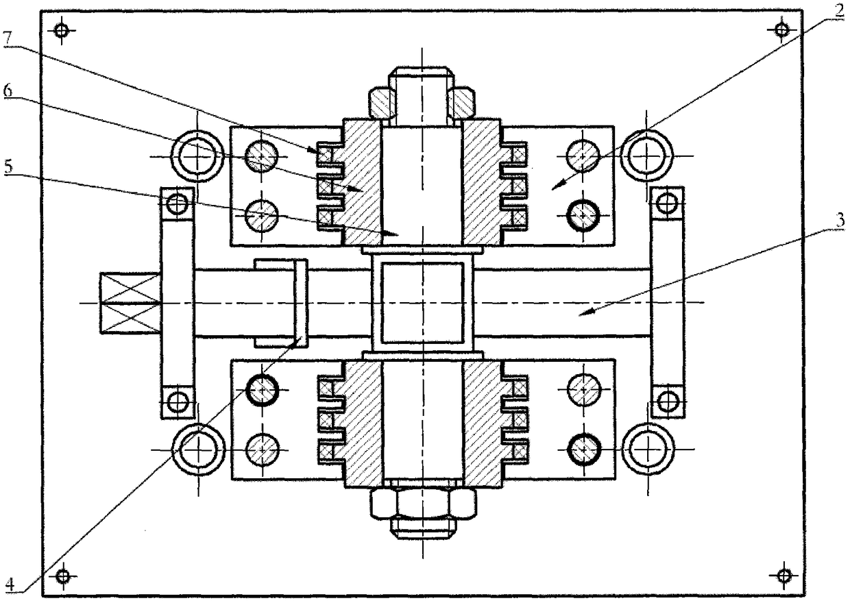
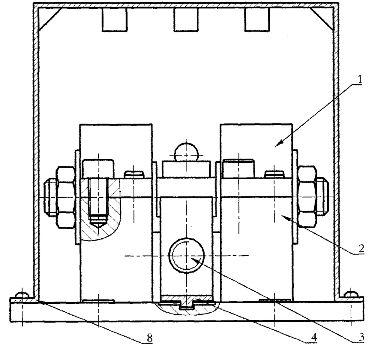
[0040] Such as figure 1 , figure 2 and image 3 As shown, a vibrating table device for testing the dynamic characteristics of annular damping parts of the present invention includes a vibrating table, an upper base 1, a lower base 2, a test calibration rod 3, a test calibration block 4, a test shaft 5, a shaft sleeve 6 and a thermal insulation Cover 8. The vibrating table adopts the existing one.

[0041] Such as Pic 4-1 , Figure 4-2 , Figure 4-3 As shown, the upper base 1 in the present invention is a semi-circular structure with flanges on both sides, the center of the upper base 1 is a concave semi-cylindrical surface, and the concave semi-cylindrical surface of the upper base 1 is processed with Multi-track annular positioning groove I9, the groove depth of multi-track annular positioning groove I9 ​​is ​​the same, ...


PUM


Abstract

The present invention relates to an annular damping parts dynamic characteristic test vibration table device for testing the annular damping parts of different specifications and materials. The vibration table device comprises upper pedestals (1), a lower pedestal (2), a test calibration rod (3), a test calibration block (4), a test shaft (5) and shaft sleeves (6). The lower pedestal (2) is fixed on the vibration table, the two upper pedestals (1) are fixed on the lower pedestal (2) separately, and the annular positioning grooves II (9) of the upper pedestals (1) and the annular positioning grooves III (14) of the lower pedestal (2) form enclosed annular grooves. The two shaft sleeves (6) sleeve at the two ends of the test shaft (5) respectively, and a plurality of to-be-tested annular damping parts (7) sleeve on the shaft sleeves (6) orderly and are located in the enclosed annular grooves. The test calibration block (4) sleeves the test calibration rod (3) via screw threads, the side surface of the test calibration block (4) is contacted with the side surface at the middle part of the test shaft (5), and an insulation cover (8) is in snap joint with the bottom of the lower pedestal (2).

Description

technical field [0001] The invention belongs to the technical field of machinery, and in particular relates to a vibration table device for testing the dynamic characteristics of an annular damping part. Background technique [0002] During the operation of mechanical equipment, vibration will cause alternating stress inside the components of the equipment, causing fatigue failure of the components and causing great damage to the equipment. Therefore, when necessary, a vibration damping structure should be added to the mechanical equipment to reduce the vibration of the equipment and reduce the damage caused by mechanical vibration to the equipment. During the design process of the vibration-damping structure, the dynamic characteristics of the components in the vibration-damping structure are one of the key factors that need to be considered in the design. In a large number of mechanical equipment, the damping parts are processed into annular parts, so it is necessary to t...

Claims


Application Information

Patent Timeline
Patent Type & Authority Patents(China)
IPC IPC(8): G01M7/02
Inventor 王成林孙伟琛李晓杰张涛
Owner BEIJING WUZI UNIVERSITY
Why Eureka
Try Eureka