
A silicon microresonant accelerometer bandwidth testing system and method

An accelerometer and bandwidth testing technology, which is applied in the field of micro-inertial systems, can solve problems such as the difficulty of directly measuring the modulation frequency, and achieve the effects of convenient on-site debugging, easy portability, and improved dynamic performance

Active Publication Date: 2021-04-06
SOUTHEAST UNIV
View PDF5 Cites 0 Cited by
  • Summary
  • Abstract
  • Description
  • Claims
  • Application Information

AI Technical Summary

Problems solved by technology

[0003] Purpose of the invention: In order to solve the problem that the modulation frequency output by the silicon microresonant accelerometer is difficult to directly measure in a dynamic environment, the present invention provides a method for testing the bandwidth of the silicon microresonant accelerometer

Method used


Image

  • A silicon microresonant accelerometer bandwidth testing system and method
  • A silicon microresonant accelerometer bandwidth testing system and method
  • A silicon microresonant accelerometer bandwidth testing system and method

Examples


Embodiment Construction

[0028] The present invention will be further described below in conjunction with accompanying drawing.

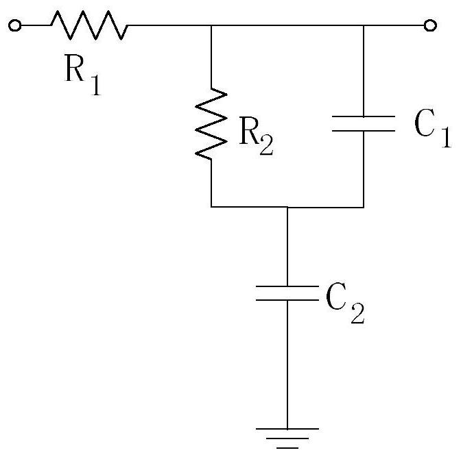
[0029] Such as Figure 1-3 , Figure 5 As shown, a silicon microresonant accelerometer bandwidth testing system of the present invention includes a phase-locked loop module composed of an exclusive-or phase detector PD, a second-order passive lead-lag loop filter LPF, and a voltage-controlled oscillator VCO , as well as high-pass filter, amplifier circuit, full-wave rectifier circuit, single-chip microcomputer and display screen; the frequency modulation signal of the dynamic acceleration test enters the XOR phase detector, and is demodulated by the phase-locked loop module, and the loop filter two After the first-order passive lead-lag output voltage passes through a high-pass filter, an amplifier circuit, and a full-wave rectifier circuit, the single-chip microcomputer performs AD sampling on the DC, and displays it on the oled display. Figure 5 For the phase-locked lo...


PUM


Abstract

A silicon microresonant accelerometer bandwidth testing system of the present invention includes a phase-locked loop module composed of an XOR phase detector, a second-order passive lead-lag loop filter, a voltage-controlled oscillator, a high-pass filter, and an amplifier. Circuit, full-wave rectification circuit, single-chip microcomputer and display screen; the frequency modulation signal of the acceleration dynamic test enters the XOR phase detector, and is demodulated by the phase-locked loop module, and the second-order passive lead-lag output voltage of the loop filter After a high-pass filter, an amplifying circuit, and a full-wave rectification circuit, the single-chip microcomputer performs AD sampling on the direct current. The invention realizes a circuit bandwidth design and test, adopts a phase-locked loop demodulation method, avoids the use of expensive high-speed frequency measurement equipment, is low in cost, is easy to carry, facilitates on-site debugging, and realizes the dynamic characteristic test of the frequency output sensor. From the perspective of the measurement and control circuit, according to the application needs, the circuit parameters are optimized according to the amplitude-frequency characteristics of the measurement and control circuit, and the dynamic performance of the resonant acceleration sensor is improved.

Description

technical field [0001] The invention relates to the field of micro-inertial systems, in particular to a silicon micro-resonance accelerometer bandwidth testing system and method. Background technique [0002] Silicon microresonant accelerometers are widely used in civil, military, aerospace and other aspects due to their small size, easy integration, low power consumption, high sensitivity, and long life. The silicon microresonant accelerometer reflects the change of acceleration by detecting the change of the resonant frequency of the resonant beam, and the output signal is a digital signal, which can be directly entered into the digital system for digital processing. The dynamic performance of the sensor is an important criterion to measure its performance, which determines whether the sensor can be applied in a specific occasion. The bandwidth of the accelerometer is reflected in the frequency deviation of the modulation frequency output by the sensor in the dynamic test...

Claims


Application Information

Patent Timeline
Patent Type & Authority Patents(China)
IPC IPC(8): G01P21/00
Inventor 李宏生张基强丁徐锴黄丽斌范书聪
Owner SOUTHEAST UNIV
Learn More