

An ionospheric side scatter detection method
A side scattering and detection method technology, applied in the field of ionospheric detection, can solve problems such as unevenness and affecting radar performance, and achieve the effect of accurate acquisition and shortening the development cycle
Inactive Publication Date: 2014-05-28
THE 22ND RES INST OF CHINA ELECTRONICS TECH GROUP CORP
View PDF0 Cites 3 Cited by
- Summary
- Abstract
- Description
- Claims
- Application Information
AI Technical Summary
Benefits of technology
This patented technology allows astronomers to detect space objects on their own footage by scanning through radio waves from multiple directions around them while measuring changes caused by these movements or other factors such as atmospheric conditions (temperature). It also helps identify areas where there are no electromagnetic radiation sources like microwaves. Overall this technique makes possible precise analysis of both terrestrial and satellite signals without interfering with any nearby electronic devices.
Problems solved by technology
This patented technical problem addressed in this patents relating to space communication networks involves developing high precision radionavigation receivers capable of accurately identifying objects under varying weather or atmospheric turbulence levels during both daylight and night vision operations without sacrificial revenue due to increased interference caused by other sources like terrestrial radiation fields. Current methods involve analyzing antenna return signatures obtained from multiple transmitters placed near the same location but separated far enough apart to avoid weakness against low altitudes approaching enemy bases.
Method used
View moreImage
Smart ImageViewing Examples

Examples
no. 1 example
Login to View More PUM
 Abstract
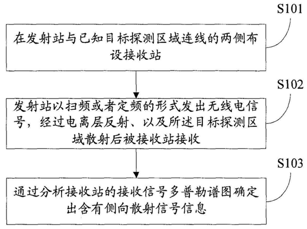
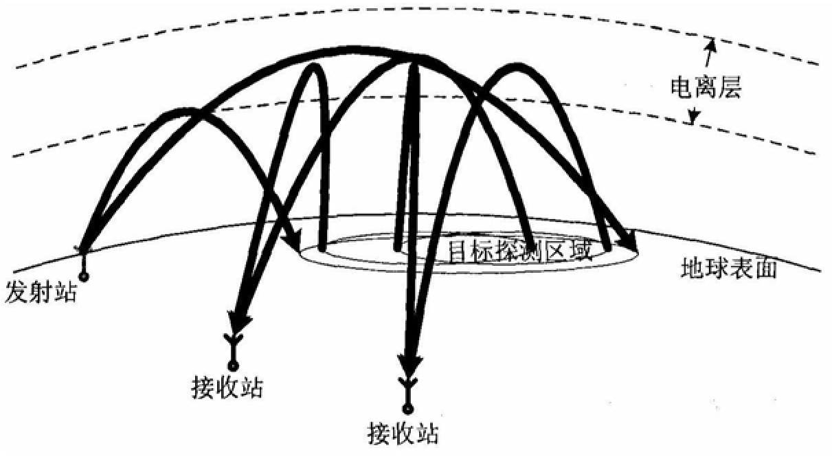
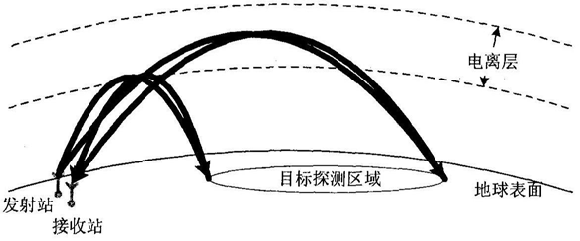
The invention discloses an ionospheric side scatter detection method, which includes: arranging receiving stations on both sides of the line connecting the transmitting station and the known target detection area; transmitting radio signals sent by the transmitting station, reflected by the ionosphere, and detecting the target After the area is scattered, it is received by the receiving station; by analyzing the Doppler spectrum of the received signal at the receiving station, it is determined that it contains side scatter signal information. The invention provides a new ionospheric detection method and lays the foundation for the ionospheric network detection. The invention can provide technical support for the ionospheric diagnosis of the sky-wave over-the-horizon radar network detection, so that the sky-wave over-the-horizon radar network detection can exert greater advantages, and greatly shorten the development cycle of the sky-wave over-the-horizon radar network system.
Description
Login to View More Claims
Login to View More Application Information
Patent Timeline
 OwnerTHE 22ND RES INST OF CHINA ELECTRONICS TECH GROUP CORP