Light bar and backlight module including the light bar

A light bar and LED lamp technology, which is applied in the field of backlight modules, can solve the problems of part offset, poor welding, and high production costs, and achieve the effects of improving assembly efficiency, high installation efficiency, and low use cost.

Active Publication Date: 2019-03-19
KUSN INFOVISION OPTOELECTRONICS
View PDF5 Cites 0 Cited by
  • Summary
  • Abstract
  • Description
  • Claims
  • Application Information

AI Technical Summary

Problems solved by technology

During the welding process, there are defects such as poor welding, part deviation, unqualified straightness, and insufficient push-pull force. If one LED light 1 is damaged or dead, the entire light bar will be scrapped, the production cost is high, and maintenance is difficult; in addition, replacement For other types of products, it is necessary to redesign the graphics of the substrate 2, which increases the loss of materials and man-hours, inconvenient operation, and poor versatility

Method used


Image

  • Light bar and backlight module including the light bar
  • Light bar and backlight module including the light bar
  • Light bar and backlight module including the light bar

Examples


Embodiment 1

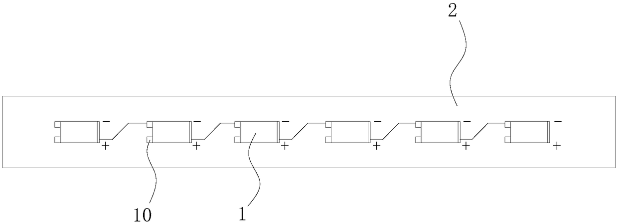
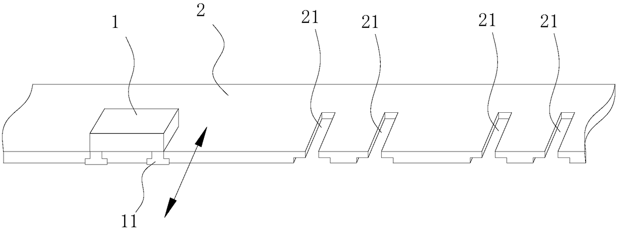
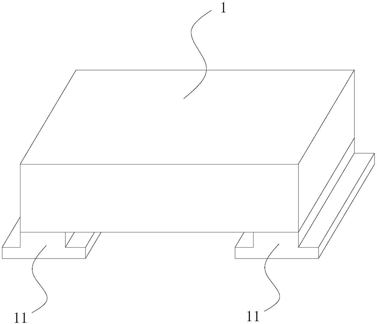
[0029] The preferred embodiment discloses a light bar. Such as figure 2 and image 3 As shown, the light bar includes an LED lamp 1 and a substrate 2, and a plurality of pairs of U-shaped slots 21 are provided on the substrate 2, and the U-shaped slots 21 form openings on one side of the substrate 2; There are a pair of clamping blocks 11, and the pair of clamping blocks 11 on an LED lamp 1 are matched with a pair of U-shaped clamping grooves 21, and the clamping blocks 11 can slide in and out along the U-shaped clamping groove 21 in the plane where the substrate 2 is located (Such as figure 2 As shown by the middle arrow), the U-shaped slot 21 can limit the movement of the LED lamp 1 in a direction perpendicular to the substrate 2 .

[0030] The LED lamp 1 can slide in and out of the U-shaped card slot 21 through the block 11 on it, and be fixed on the substrate 2 through the U-shaped card slot 21. The LED lamp 1 is easy to disassemble, has high disassembly efficiency, a...

Embodiment 2

[0044]This preferred embodiment discloses a backlight module, including the light bar as described in the first preferred embodiment. The LED light on the light bar is easy to disassemble and assemble. When a certain LED light is not on, you can only replace the damaged light without scrapping the entire light bar, which reduces the cost of use and improves the replacement efficiency of the light bar; The installation efficiency of the LED lamp is high, thereby improving the assembly efficiency of the backlight module.


PUM


Abstract

The invention discloses a light bar and a backlight module including such light bar, belongs to the technical field of backlight modules, and is designed in order to solve the problems of low production efficiency and a high scrappage, etc., of an existing device. The light bar comprises an LED lamp and a base plate. A plurality of pair of U-shaped necks are arranged in the base plate, and the U-shaped necks are provided with openings in one lateral side of the base plate; a pair of clamping blocks are welded on the LED lamp, the pair of clamping blocks on the LED lamp are adaptive to one pair of U-shaped necks, the clamping blocks can slide in and out along the U-shaped necks, and the U-shaped necks can limit movement of the LED lamp in a direction perpendicular to the base plate. The light bar and the LED lamp of the backlight module including such light bar are convenient to demount and are high in demounting efficiency, the damaged LED lamp can be replaced independently without a need to scrap the whole light bar, and cost is reduced, the LED lamp and the base plate are connected stably and vibration resistance is high.

Description

technical field [0001] The invention relates to the technical field of backlight modules, in particular to a light bar and a backlight module including the light bar. Background technique [0002] The main structure of the light bar is that a plurality of LED lights are sequentially arranged on the substrate (PCB board), and the plurality of LED lights are basically arranged in a straight line. [0003] Such as figure 1 As shown, in the existing light bar, the LED lamp 1 is welded on the substrate 2 , that is, the LED lamp 1 is fixed on the substrate 2 through the welding spot 10 to complete the welding. During the welding process, there are defects such as poor welding, part deviation, unqualified straightness, and insufficient push-pull force. If one LED light 1 is damaged or dead, the entire light bar will be scrapped, the production cost is high, and maintenance is difficult; in addition, replacement For other types of products, it is necessary to redesign the graphics...

Claims


Application Information

Patent Timeline
Patent Type & Authority Patents(China)
IPC IPC(8): F21S4/28F21V17/16F21Y103/10F21Y115/10
CPCF21V17/164
Inventor 李国亮任媛媛张娟娟黄磊
Owner KUSN INFOVISION OPTOELECTRONICS
Why Eureka
Try Eureka