Sliding core device

A sliding type and core technology, which is applied in the field of sliding core devices, can solve the problems of setting countersunk holes, hindering the smooth movement of sliding cores, fixing core guide parts, etc., and achieving the effect of avoiding interference

Inactive Publication Date: 2017-02-22
MISUMI
View PDF6 Cites 0 Cited by
  • Summary
  • Abstract
  • Description
  • Claims
  • Application Information

AI Technical Summary

Problems solved by technology

[0010] However, in the sliding core device of Patent Document 1, even when the guide hole and the like are provided on the sliding core side and the groove-like recesses are provided on the core guide side, there is actually a difficulty in Problem with inserting bolts on one side of the sliding core to secure the core guide to the movable mold
That is, since there are groove-like recesses on the bottom surface of the rail portion of the

Method used


Image

  • Sliding core device
  • Sliding core device
  • Sliding core device

Examples


Embodiment Construction

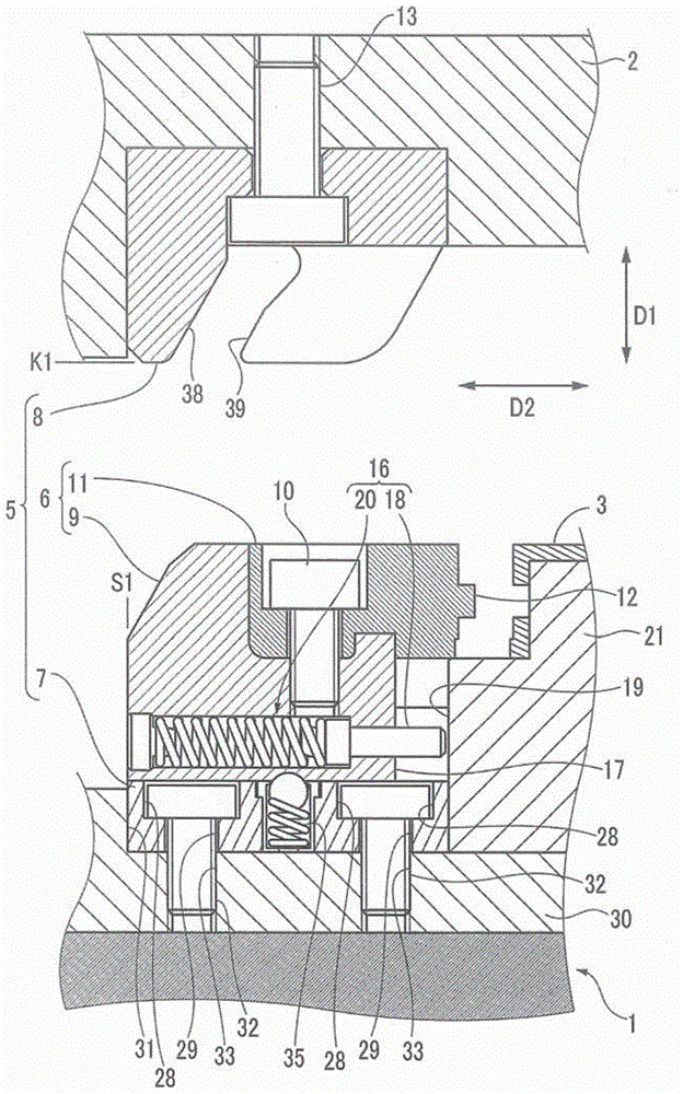
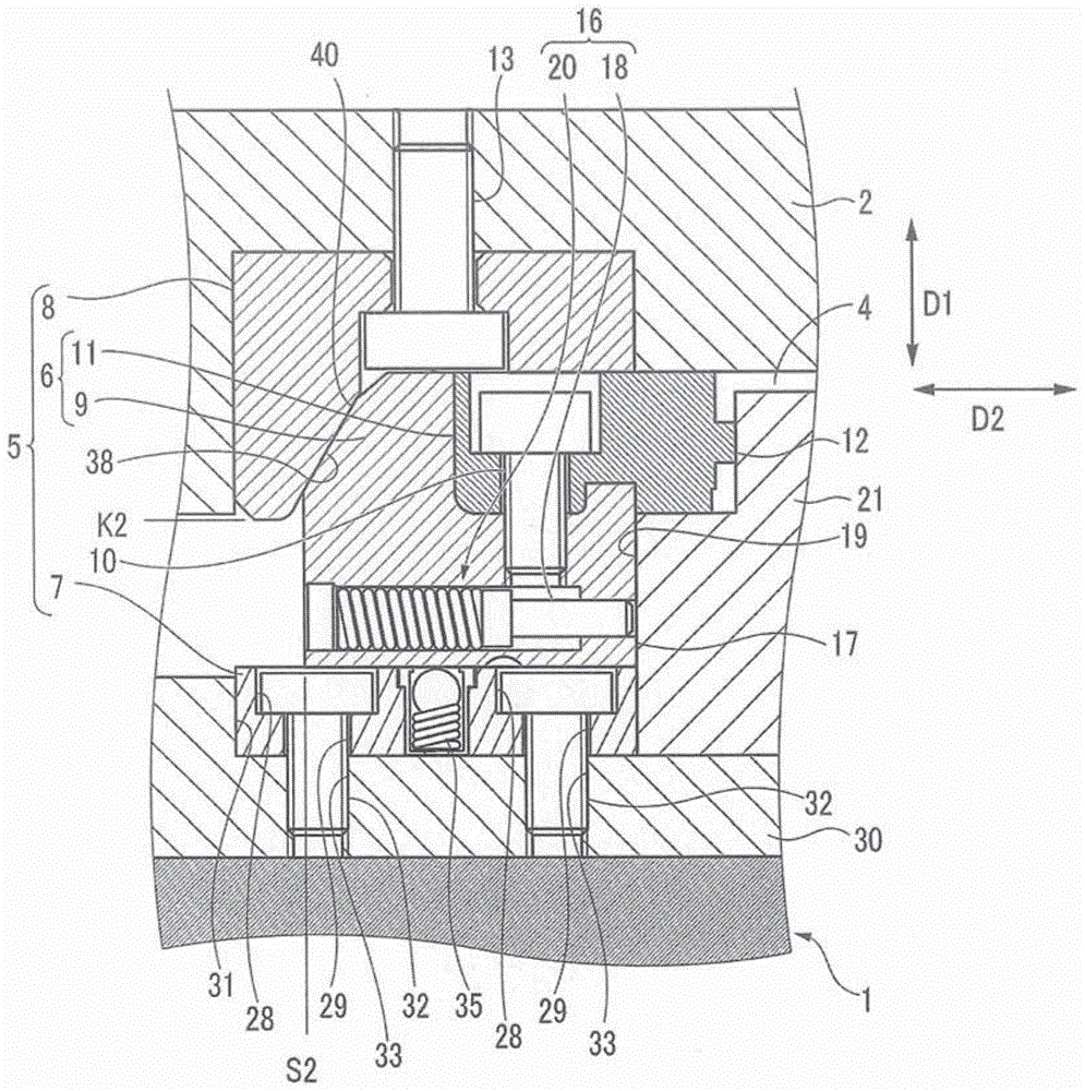
[0072] Hereinafter, embodiments of the present invention will be described with reference to the drawings. figure 1 It is a cross-sectional view of a part of a mold having a sliding core device according to an embodiment of the present invention. like figure 1 As shown, the mold has a first parting mold 1 and a second parting mold 2 which are opened and closed in a first direction D1 , and a sliding core arrangement 5 . Sliding core device 5 forms cavity 4 ( figure 2 ), the cavity 4 is used to form the molded product 3 together with the first split mold 1 and the second split mold 2. Here, by driving the first split mold 1, the first split mold 1 and the second split mold 2 are opened or closed.

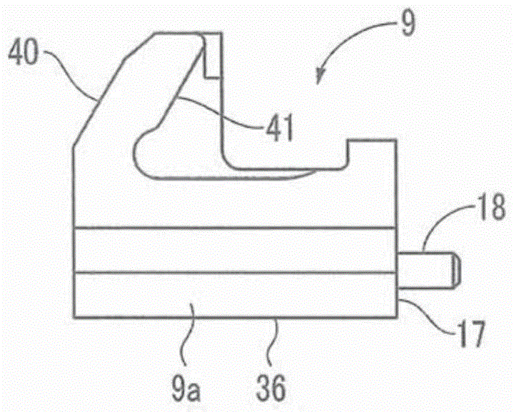
[0073] The slide core device 5 includes a slide core 6 , a core guide 7 , and a cam 8 . The sliding core 6 is moved on the first split mold 1; the core guide 7 can slide the core 6 between the retreat position S1 and the molding position S2 ( figure 2 ) to guide the sliding co...


PUM


Abstract

The invention provides a sliding core device. The slide core device (5) includes a core guide (7) and a force application mechanism (16). The core guide (7) guides the sliding core (6) in such a manner as to be movable between the forming position S2 and the retracted position S1. (16) is provided in the slide core (6), and the slide core (6) is biased from the molding position S2 to the retracted position S1.The force application mechanism(16) is provided in the sliding core (6), force is applied on the sliding core (6) by the force application mechanism (16) from the molding position S2 to the retracted position S1.

Description

technical field [0001] The present invention relates to a slide core device that includes a slide core provided in a mold for molding and drives the slide core. Background technique [0002] As such a sliding core device, the following device is known: the device is equipped with a core guide portion fixed on the movable side parting surface of the mould, along a sliding direction intersecting with the opening and closing direction of the mould. Guide the sliding core. The core guide part has a groove-shaped guide rail part, and the guide rail part is engaged with the guided part formed on the slide core to guide the slide core along the above-mentioned sliding direction. The slide core is guided so as to be movable between a molding position of the cavity and a retracted position separated from the molding position (for example, refer to Patent Document 1). [0003] The sliding core device of Patent Document 1 is provided with an urging mechanism for urging the sliding co...

Claims


Application Information

Patent Timeline
IPC IPC(8): B29C45/33
CPCB29C45/33B29C45/332B29C2045/336
Inventor 市川泉有田彰
Owner MISUMI
Why Eureka
Try Eureka