Joint board, foam applying mechanism and foam applying arranging device

A finishing device and foam technology, which is applied in the processing of textile materials, processing of textile material carriers, and the use of liquid textile materials with a small bath ratio, etc., can solve problems such as uneven color, applying foam, elastic fabric curling, etc., to achieve foam uniform effect

Pending Publication Date: 2017-02-22
上海技楷机电设备有限公司
View PDF5 Cites 2 Cited by
  • Summary
  • Abstract
  • Description
  • Claims
  • Application Information

AI Technical Summary

Problems solved by technology

[0005] However, this foam applicator has the following disadvantages: 1. The foam is in a state of continuous attenuation during the conveying process. When the foam is divided into multiple paths from one path at the foam conveying part, uneven attenuation occurs, and the foam with a large attenuation is heavier. The foam attached to the inner wall of the pipeline rolls forward, while the foam with a small attenuation is lighter and advances in the middle of the pipeline. The heavier part of the foam is located at both ends of the slit when it flows out of the slit of the foam distribution box, and the lighter part is located in the slit.

Method used


Image

  • Joint board, foam applying mechanism and foam applying arranging device
  • Joint board, foam applying mechanism and foam applying arranging device
  • Joint board, foam applying mechanism and foam applying arranging device

Examples


Embodiment Construction

[0025] The present invention will be described in detail below in conjunction with the accompanying drawings.

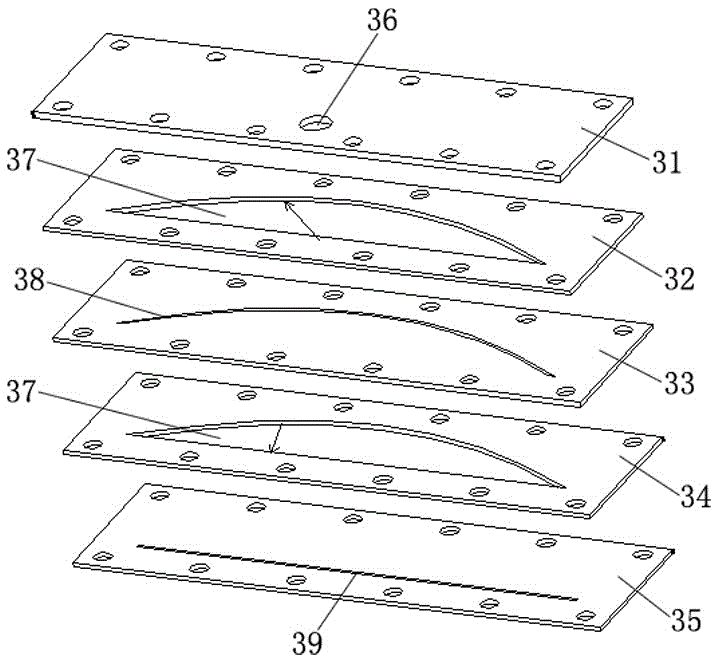
[0026] like figure 1 As shown, a seam plate 19 includes a first plate 31, a second plate 32, a third plate 33, a fourth plate 34 and a fifth plate 35 that are stacked and connected together from top to bottom. , the first plate 31 is provided with a through hole 36 as a foam inlet, the second plate 32 is provided with a sub-arc arcuate notch 37, and the third plate 33 corresponds to the arc of the inferior arc arcuate notch 37 of the second plate 32 The edge is provided with a parabolic gap 38 that runs through front and back, the fourth plate 34 is provided with a inferior arc arcuate notch 37 that is as large as the inferior arc arcuate notch 37 of the second plate 32, and the fifth plate 35 corresponds to the fourth plate The inline edge of the inferior arc arcuate notch 37 of 34 is provided with a long strip slit 39 that runs through front and back as a foam out...


PUM


Abstract

The invention discloses a joint board, a foam applying mechanism and a foam applying arranging device. The joint board comprises a first board piece, a second board piece, a third board piece, a fourth board piece and a fifth board piece which are sequentially stacked and connected together from top to bottom. The first board piece is provided with a through hole adopted as a foam inlet, the second board piece is provided with an inferior arc arch gap, the third board piece is provided with a front-back through parabolic crack, the fourth board piece is provided with an inferior arc arch gap, and the fifth board piece is provided with a front-back through long-strip-shaped crack adopted as a foam outlet. The joint board can enable the foam conveying path continues to be attenuated uniformly. The foam applying mechanism comprises a supporting frame, the joint board installed on the supporting frame and a long-strip-shaped scraper arranged on the joint board, a knife edge of the scraper is provided with a foam outlet, the foam inlet of the joint board is communicated with a foam input pipe, and the foam outlet of the joint board is communicated with the foam outlet of the scraper. The foam applying arranging device comprises a machine frame, the foam applying mechanism, an edge sealing mechanism and a control circuit.

Description

technical field [0001] The invention relates to the technical field of textile printing and dyeing processing equipment, in particular to a slit plate, a foam applying mechanism and a foam applying and finishing device, which are used for applying foam to continuously processed textile fabrics during the textile printing and dyeing process. Background technique [0002] Traditional textile printing and dyeing processing usually includes mercerizing, dyeing, finishing and printing steps, and these processing steps require water as a medium to dilute chemicals. During the processing process, the textile fabric carries a high amount of water, and finally consumes a lot of energy to dry the water, and the chemicals are left on the surface of the textile fabric to achieve the required printing and dyeing effect. [0003] In order to reduce energy consumption, a foam application device has appeared in the prior art, which uses foam as a medium to carry chemicals and apply them to ...

Claims


Application Information

Patent Timeline
IPC IPC(8): D06B19/00D06B23/04
CPCD06B19/0094D06B23/04
Inventor 韩云岗
Owner 上海技楷机电设备有限公司
Why Eureka
Try Eureka