Method for applying horizontal directional drilling to refuse landfill leachate drainage

A technology of landfill and horizontal directional drilling, which is used in protection devices, buildings, infrastructure projects, etc., can solve the problem of the large amount of horizontal seepage and drainage shaft projects and the large amount of horizontal seepage blind trench excavation projects. , destroying the stability of the heap and the surrounding environment, etc., to achieve the effect of being conducive to drainage consolidation, good splicing strength, and good adaptability

Inactive Publication Date: 2017-02-22
上海胜义环境科技有限公司
View PDF4 Cites 6 Cited by
  • Summary
  • Abstract
  • Description
  • Claims
  • Application Information

AI Technical Summary

Problems solved by technology

In addition, the excavation of horizontal infiltration blind ditch is relatively large
This will result in a large amount of engineering for horizontal infiltration plus pumping and drainage shafts, which will take a long time and be expensive
[0005] 2. The pumping shaft needs to be pumped continuously, so the operating cost is high and energy consumption is high
[0006] 3. The excavation of the horizontal infiltration blind ditch and the pumping and drainage shaft will affect the garbage body and the surrounding environment. There are gaps around the shaft for cleaning and diversion and gas collection. During the construction period, the stability of the pile and the surrounding environment may also be damaged sex, there is a security risk

Method used


Image

  • Method for applying horizontal directional drilling to refuse landfill leachate drainage
  • Method for applying horizontal directional drilling to refuse landfill leachate drainage
  • Method for applying horizontal directional drilling to refuse landfill leachate drainage

Examples


Embodiment Construction

[0019] In order to make the technical means, creative features, goals and effects achieved by the present invention easy to understand, the present invention will be further described below in conjunction with specific embodiments.

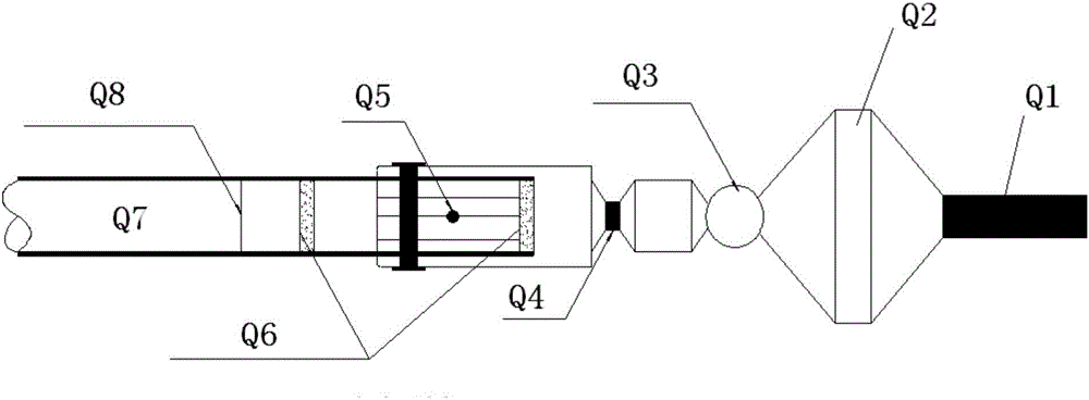
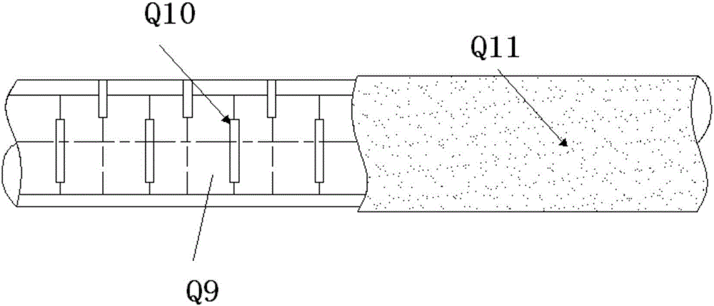
[0020] The horizontal directional drilling rig mechanism utilized in the method for the horizontal directional drilling of the present invention to be applied to the leachate drainage in the landfill (hereinafter referred to as "the method") can be found in figure 2 As shown, the horizontal directional drilling machine has a drill pipe Q1, the drill pipe Q1 is connected to the reamer Q2, the reamer Q2 is equipped with a rotary joint Q3, and the rotary joint Q3 is connected to the drawing head through the soft joint Q4, and the drawing head installation guide Seepage pipe Q7, the pipe head is installed with flexible waterproof material plugging Q6 through the set screw Q5, the figure shows the connection position Q8 between the seepage pipe Q7 and ...


PUM


Abstract

The invention discloses a method for applying horizontal directional drilling to refuse landfill leachate drainage. The method comprises the steps that a drill hole of K meters is drilled in the part, in a preset low-point position of a side slope of a refuse dam, of a refuse dump body by a horizontal directional drilling rig, a leachate guiding pipe is carried by a drill bit of the horizontal directional drilling rig to enter the drill hole and enter the refuse dump body along with the drill bit, and finally a leachate drainage channel is formed; and the pipe body, located within the range from the front end to the position away from the front end of the leachate guiding pipe by S meters, of the leachate guiding pipe is of a floral pipe structure wrapped with geotextile, grooves are formed in the two sides and the top of the floral pipe structure at intervals, wherein S is smaller than K. According to the method for applying horizontal directional drilling to refuse landfill leachate drainage, the horizontal directional drilling technology is introduced into the field of refuse landfill leachate drainage and combined with the refuse landfill leachate drainage technical characteristics, so that an artesian leachate drainage facility is formed, the phreatic line is effectively lowered, and drainage consolidation of stockpiling refuse is facilitated; and the method has the advantage of being easy and convenient to construct, low in manufacturing cost and the like.

Description

technical field [0001] The invention relates to the field of drainage of municipal solid waste landfills, in particular to a method for horizontal directional drilling applied to drainage of leachate in garbage landfills. Background technique [0002] The landfill is a place where domestic waste is disposed of in a sanitary landfill, and geotechnical materials are often used for anti-seepage. The landfill waste disposal method is the main waste disposal method in my country because of its low cost and good sanitation conditions. According to the requirements of the industry standard CJJ-17, domestic waste landfills in my country should be provided with a diversion layer and blind ditch as a leachate collection system to discharge leachate from the landfill or due to rainfall. However, as the service life of the landfill increases, the drainage function of the leachate infiltration facilities at the bottom will continue to decline, and even blockage will occur, resulting in ...

Claims


Application Information

Patent Timeline
Patent Type & Authority Applications(China)
IPC IPC(8): E02D31/00
CPCE02D31/00
Inventor 刘宁何家能
Owner 上海胜义环境科技有限公司
Why Eureka
Try Eureka