Blasting compaction device and soil slope blasting compaction method thereof

A soil slope and blasting pressure technology, which is applied in the field of soil slope blasting compaction and blasting compaction devices, can solve the problems of not giving full play to the high-quality performance of soil, large overall engineering quantity, and inability to deal with soil intrusion, etc.

Active Publication Date: 2021-09-10
CHINA NO 15 METALLURGICAL CONSTR GRP
View PDF8 Cites 0 Cited by
  • Summary
  • Abstract
  • Description
  • Claims
  • Application Information

AI Technical Summary

Problems solved by technology

[0002]Slope support is a key project in earthworks. Permanent slopes often need to be supported and reinforced, especially for slopes with poor soil quality. Weak soil slopes need to be reinforced to prevent slope safety accidents; currently commonly used slope support methods include: slope cutting and load reduction method, spray anchor reinforcement method, stone masonry or concrete face protection method, retaining wall method etc.; the above method has the following problems in slope support: 1. The soil properties are not changed, and some of the high-quality properties of the soil are not brought into play; 2. The intrusion of deep groundwater to the soil cannot be dealt with through external plugging and prevention methods; 3. 1. The slope can only be treated in the shallow layer, and the middle and deep layer of the slope cannot be reinforced; 4. The overall engineering volume is large, the construction period is long, and the cost is high; in order to solve the above problems, a blasting compaction device and its effect on the soil edge Slope blasting compaction method

Method used


Image

  • Blasting compaction device and soil slope blasting compaction method thereof
  • Blasting compaction device and soil slope blasting compaction method thereof
  • Blasting compaction device and soil slope blasting compaction method thereof

Examples


Embodiment Construction

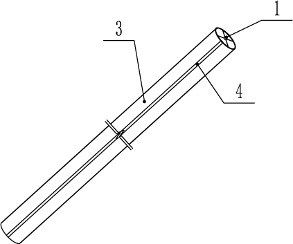
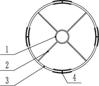
[0033] see Figure 1-6 , the present embodiment is a blasting compaction device, a blasting compaction device, comprising a charge 1, and a plurality of positioning cards 2 are arranged around the charge 1, and the positioning cards 2 are combined with the charge 1 to form an explosive propulsion device , the outer end of the explosive propulsion device is correspondingly provided with a plurality of stamped arc-shaped plates 3, and a connecting device 4 is arranged between the stamped arc-shaped plates 3, and the stamped arc-shaped plates 3 are connected in pairs by the connecting device 4; Both the positioning card 2 and the connecting device 4 are fragile materials.

[0034] In this embodiment, the drug column 1 is an emulsified drug roll, and the diameter of the emulsified drug roll is 20 mm.

[0035] In this embodiment, the positioning card 2 is a circular hollow tubular structure integrally formed with four legs at an angle of 90 degrees to each other, and is used to fi...


PUM


Abstract

The invention relates to a blasting compaction device and a soil slope blasting compaction method thereof. The blasting compaction device comprises a grain, a plurality of positioning clamps are arranged on the periphery of the grain, the positioning clamps and the grain are combined to form an explosion pushing device, a plurality of stamping arc-shaped plates are correspondingly arranged at the outer end of the explosion pushing device, connecting devices are arranged among the stamping arc-shaped plates, every two stamping arc-shaped plates are connected through the corresponding connecting device, and the positioning clamps and the connecting devices are all made of fragile materials. According to the blasting compaction device and the soil slope blasting compaction method thereof, the problems that in the prior art, the soil property is not changed, the invasion of deep underground water to the soil body cannot be treated, only shallow treatment can be carried out on the side slope, the middle-deep layer of the side slope cannot be reinforced, the overall project amount is large, the construction period is long, and the manufacturing cost is high are solved; and the blasting compaction device and the soil slope blasting compaction method thereof have the functions that the work amount is small, the construction period is short, the soil density is changed, the influence of depth is avoided, and the underground water drainage function is achieved.

Description

technical field [0001] The invention relates to construction fields such as buildings, roads and bridges, municipal administration, and mining, and in particular relates to a blasting compaction device and a method for blasting and compacting soil slopes. Background technique [0002] Slope support is a key project in earthworks. Permanent slopes often need to be supported and reinforced, especially for bad soil slopes. We must reinforce weak soil slopes to prevent slope safety accidents Occurrence; The slope support methods commonly used at present include: slope cutting and load reduction method, spray anchor reinforcement method, stone masonry or concrete face protection method, retaining wall method, etc.; the above-mentioned methods have the following problems in slope support: 1 1. The properties of the soil have not been changed, and some of the high-quality properties of the soil have not been brought into play; 2. The intrusion of deep groundwater to the soil cannot...

Claims


Application Information

Patent Timeline
Patent Type & Authority Applications(China)
IPC IPC(8): F42D1/08F42D3/00
CPCF42D1/08F42D3/00
Inventor 曹军梁博
Owner CHINA NO 15 METALLURGICAL CONSTR GRP
Why Eureka
Try Eureka