Pipe pile with incomplete ribs

A non-integral, pipe pile technology, applied in sheet pile wall, building, foundation structure engineering, etc., can solve the problems of obvious soil squeeze effect, no obvious improvement in the physical and mechanical properties of soft soil, complicated construction plan, etc. Test the effect of sensors, accelerate the drainage and consolidation of soft soil, and improve the bearing capacity of single piles

Active Publication Date: 2016-10-12
苏义民
View PDF7 Cites 0 Cited by
  • Summary
  • Abstract
  • Description
  • Claims
  • Application Information

AI Technical Summary

Problems solved by technology

However, when it is used to deal with soft foundations, it is impossible to ensure that the walls of the soft soil holes stand upright. The construction plan is complicated, and the holes must be drilled first, and problems such as hole collapse and diameter reduction are unavoidable.
[0003] In short, the pipe pile scheme currently used for soft soil foundation treatment either uses the hammering method or the static pressure method to sink the pipe pile into the soft soil, and relies on the bearing capacity provided by the pile tip bearing layer of the pipe pile to meet the needs of the project, but the squeeze The soil effect is obvious, which does not significantly improve the physical and mechanical properties of the soft soil itself; or use the pre-drilling method to sink the pipe pile into the soft soil. Although the soil squeezing effect can be avoided, the standing of the hole wall cannot be guaranteed. The process of filling sand between the hole wall and the pipe wall cannot be implemented, and there are still many problems

Method used


Image

  • Pipe pile with incomplete ribs
  • Pipe pile with incomplete ribs
  • Pipe pile with incomplete ribs

Examples


Embodiment Construction

[0029] The content of the present invention will be described below in conjunction with specific embodiments.

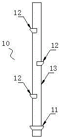
[0030] Such as Figure 1~Figure 5 As shown, the pipe pile with incomplete ribs described in the present invention includes: a hollow body 13 of the pipe pile 10, a first rib 11 is provided at the bottom of the body 13, and the first rib 11 starts from the bottom on the outside of the body 13. There are a plurality of ribs 12 distributed upward, and the ribs 12 are distributed in a staggered manner according to the outside of the main body 13 .

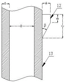
[0031] Such as image 3 As shown, a rib is composed of elements such as rib integrity, rib height C, rib thickness B, rib wall thickness A, and rib working angle β. Rib integrity refers to the ratio of the angle of a rib around the body 13 of the pipe pile to 360 degrees. The rib height C refers to the height of the rib if it is extracted separately, that is, the distance from the pinch-out point where the thickness of the...


PUM


Abstract

The invention discloses a pipe pile with incomplete ribs. When the pipe pile is used in soft soil, a total-communicating space is formed between the pipe pile and the soft soil, and sand or other substitutions are poured between the pipe pile and the soft soil. The pipe pile with the incomplete ribs is characterized by comprising a hollow pipe pile body; the bottom of the pipe pile body is provided with an initial rib; a plurality of common ribs are distributed on the outer side of the pipe pile body with the initial rib as start from bottom to top and are distributed in a staggered mode along the outer side of the pipe pile body; and the common ribs are the incomplete ribs and make direct contact with the sand, and the sand forms a completely-communicating drainage channel. According to the pipe pile with the incomplete ribs, sand pouring is conducted in the pile sinking process, and a complete sand envelope is formed around the pipe pile; the complete drainage channel is constructed through the envelope together with a sand cushion arranged on the ground in a paving mode, quick releasing of pore water pressure, reducing of soil squeezing effect and drainage consolidation of the soft soil are facilitated; the bearing force of the pipe pile is increased through interaction of an envelope body and the ribs; and meanwhile, the bearing force of the pipe pile can also be increased through increasing of the side wall frictional resistance of the pipe pile.

Description

technical field [0001] The invention relates to a pipe pile for building construction, in particular to a pipe pile with incomplete ribs, and belongs to the technical field of building construction. Background technique [0002] The treatment of soft soil foundations has its own advantages and disadvantages, from bagged manholes, plastic inserts, gravel piles, powder spray piles to prestressed concrete pipe piles, etc., but none of them can be flexibly adapted to the ground conditions under one treatment method. Some are simply drainage, and some are simply relying on the improvement of pile bearing capacity to meet the requirements. The prestressed pipe piles currently used have been widely used because of their reliable pile quality, factory production, fast construction speed, and economical rationality. The soil squeezing effect produced is especially serious when it is used in a large area. Chinese patent CN 201310603224.7 provides a ribbed prestressed pipe pile and i...

Claims


Application Information

Patent Timeline
Patent Type & Authority Applications(China)
IPC IPC(8): E02D5/58E02D19/20
CPCE02D5/58E02D19/20
Inventor 苏义民
Owner 苏义民
Why Eureka
Try Eureka