Installation construction method for large all-steel formwork at internal corner of shear wall

A construction method and shear wall technology, which are applied in the direction of formwork/formwork/work frame, formwork/formwork/work frame connector, and on-site preparation of building components, which can solve the problem that the rigidity of formwork at the inner corner cannot be guaranteed. and firm, large lateral pressure, unable to solve the problems of mass production, etc., to achieve the effect of accurate size, high bearing capacity and high rigidity

Inactive Publication Date: 2012-10-03
天津住宅集团建设工程总承包有限公司
View PDF19 Cites 39 Cited by
  • Summary
  • Abstract
  • Description
  • Claims
  • Application Information

AI Technical Summary

Problems solved by technology

[0011] Although the 3rd to 5th patents have a series of advantages, they cannot solve the problem of mass production and supply to the construction site
[0015] Although the 7th and 8th patents have a series of advantages, they cannot guarantee the rigidity and deformation of the template at the inner corner when the lateral pressure is too large when pouring concrete.
Although this patent has a series of advantages, it cannot guarantee the rigidity and firmness of the template at the inner corner

Method used


Image

  • Installation construction method for large all-steel formwork at internal corner of shear wall
  • Installation construction method for large all-steel formwork at internal corner of shear wall

Examples


Embodiment 1

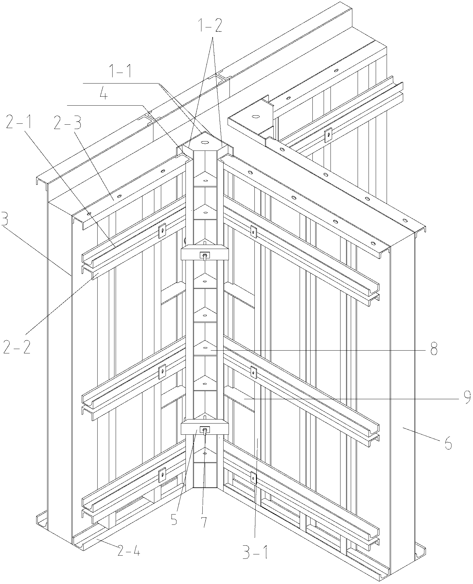
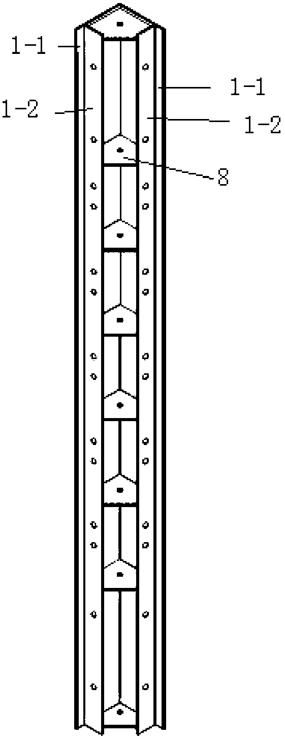
[0038] (1) Install the negative angle steel formwork at the internal corner of the wall, and the negative angle steel formwork includes two vertical steel plates 1-1 welded at right angles, and are connected at intervals along the height direction of the vertical steel plates 1-1 between the two vertical steel plates There are a plurality of reinforcing ribs 8 arranged in the horizontal direction, and a connecting steel plate 1-2 arranged in the vertical direction is respectively welded on both sides of the reinforcing ribs, and each of the connecting steel plates is respectively connected to the vertical The steel plates are vertically connected; (2) a grooved steel plate 4 is installed on the outer edge of each connecting steel plate 1-2 in the vertical direction through a screw rod connection; (3) the large steel templates on both sides of the inner corner of the installation wall 3; (4) On the large steel formwork 3, a plurality of formwork back flutes arranged along the ho...

Embodiment 2

[0041] (1) Install the negative angle steel formwork at the internal corner of the wall, and the negative angle steel formwork includes two vertical steel plates 1-1 welded at right angles, and are connected at intervals along the height direction of the vertical steel plates 1-1 between the two vertical steel plates There are a plurality of reinforcing ribs 8 arranged in the horizontal direction, and a connecting steel plate 1-2 arranged in the vertical direction is respectively welded on both sides of the reinforcing ribs, and each of the connecting steel plates is respectively connected to the vertical The steel plates are vertically connected; (2) a grooved steel plate 4 is installed on the outer edge of each connecting steel plate 1-2 in the vertical direction through a screw rod connection; (3) the large steel templates on both sides of the inner corner of the installation wall 3; (4) Install reinforcing plates 9 at regular intervals between the channel steel plate 4 and ...

Embodiment 3

[0044] (1) Install the negative angle steel formwork at the internal corner of the wall, and the negative angle steel formwork includes two vertical steel plates 1-1 welded at right angles, and are connected at intervals along the height direction of the vertical steel plates 1-1 between the two vertical steel plates There are a plurality of reinforcing ribs 8 arranged in the horizontal direction, and a connecting steel plate 1-2 arranged in the vertical direction is respectively welded on both sides of the reinforcing ribs, and each of the connecting steel plates is respectively connected to the vertical The steel plates are vertically connected; (2) a grooved steel plate 4 is installed on the outer edge of each connecting steel plate 1-2 in the vertical direction through a screw rod connection; (3) the large steel templates on both sides of the inner corner of the installation wall 3; (4) Install reinforcing plates 9 at regular intervals between the channel steel plate 4 and ...


PUM


Abstract

The invention discloses an installation construction method for a large all-steel formwork at the internal corner of a shear wall. The installation construction method comprises the following steps of: (1) installing an internal corner steel formwork at the internal corner of the wall, wherein the internal corner steel formwork comprises two vertical steel plates which are welded at a right angle, multiple reinforcing ribs are connected between the two vertical steel plates at intervals, two connecting steel plates are respectively welded at the two sides of each reinforcing rib, and each connecting steel plate is respectively and vertically connected with the vertical steel plate at the corresponding side; (2) respectively connecting and installing a groove type steel plate at the outer side edge of each connecting steel plate along the vertical direction through a lead screw; (3) installing large steel formworks at the two sides of the internal corner of the wall; (4) connecting formwork back ribs on the large steel formworks at intervals; (5) connecting internal corner rolling grooves corresponding to each reinforcing rib with holes arranged on the reinforcing ribs through internal corner hook bolts; and (6) pouring concrete into the shear wall. According to the installation construction method provided by the invention, a formwork system at the internal corner of the shear wall firmly and reliably forms a stable integral system.

Description

technical field [0001] The invention relates to the field of building templates, in particular to a construction method for installation at the inner corners of all-steel large templates for building shear walls. Background technique [0002] Large formwork was first developed and applied in France and other countries in the late 1950s. my country began to develop all-steel large formwork in the early 1970s. The all-steel large formwork currently used in my country is an assembled large formwork; the assembled large formwork can be reassembled to meet the requirements of different board sizes and improve the utilization rate of the formwork. All-steel large formwork is a new type of formwork and scaffolding technology. It is assembled into a building model with 3mm~6mm steel plates. The back and side of the steel plates are connected by matching corrugated strips and connectors to form a solid formwork structure. Compared with the traditional wooden formwork, the all-steel ...

Claims


Application Information

Patent Timeline
Patent Type & Authority Applications(China)
IPC IPC(8): E04G11/08E04G17/04
Inventor 刁晓翔陈捷孙凤龙回运力刁宁牛庆元
Owner 天津住宅集团建设工程总承包有限公司
Why Eureka
Try Eureka