Full-glass-reinforced-plastic box-type cable chute

A technology of cable trench and FRP, which is applied in the direction of cable installation, ground cable installation, pipe support, etc. It can solve the problems of inconvenient opening, inability to cross work, and large gaps, etc., so as to achieve a good working environment for cables and improve work efficiency. The effect of high surface flatness

A technology of cable trench and FRP, which is applied in the direction of cable installation, ground cable installation, pipe support, etc. It can solve the problems of inconvenient opening, inability to cross work, and large gaps, etc., so as to achieve a good working environment for cables and improve work efficiency. The effect of high surface flatness

CN102593780AInactive Publication Date: 2012-07-18SHANGHAI MUNICIPAL ELECTRIC POWER CO +2

Image

  • Full-glass-reinforced-plastic box-type cable chute
  • Full-glass-reinforced-plastic box-type cable chute
  • Full-glass-reinforced-plastic box-type cable chute

Examples


Embodiment

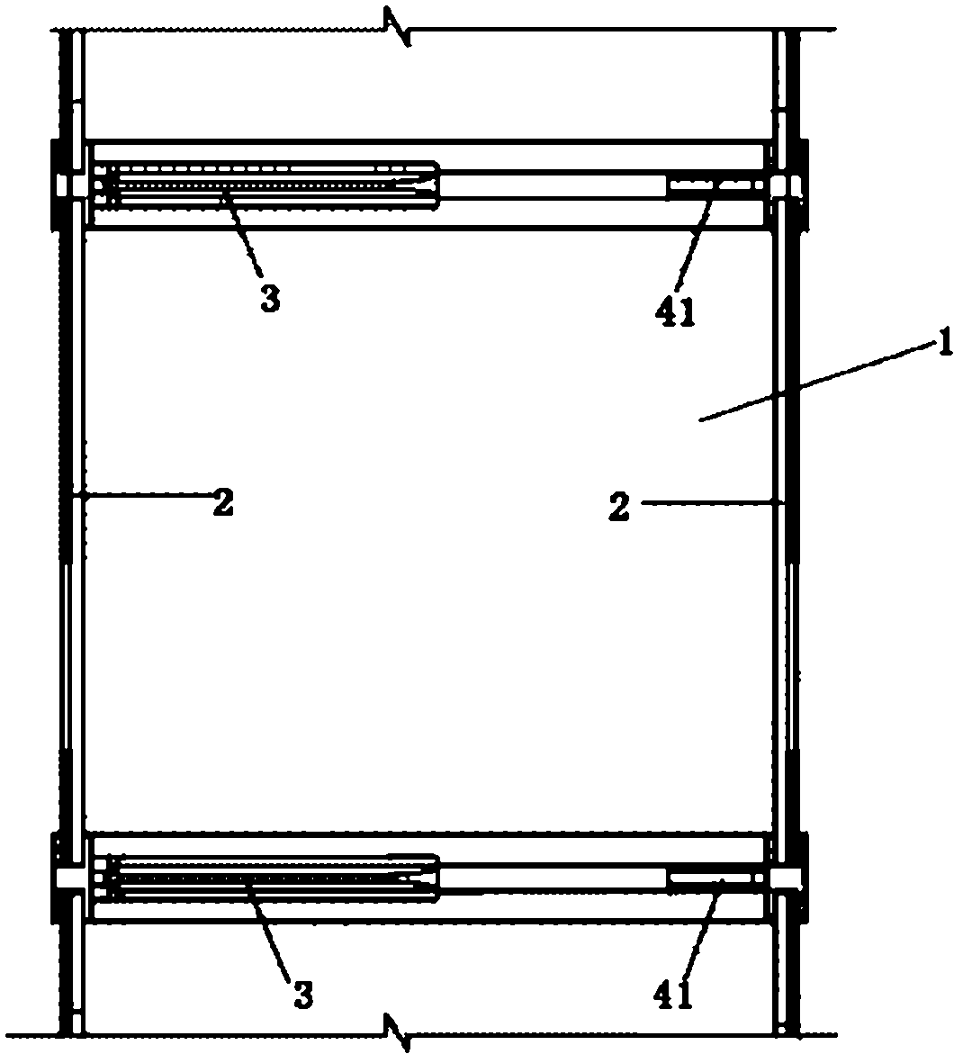
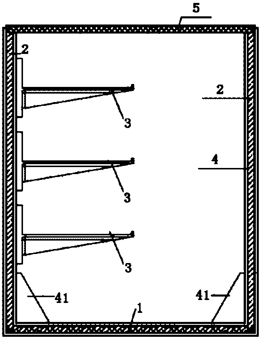
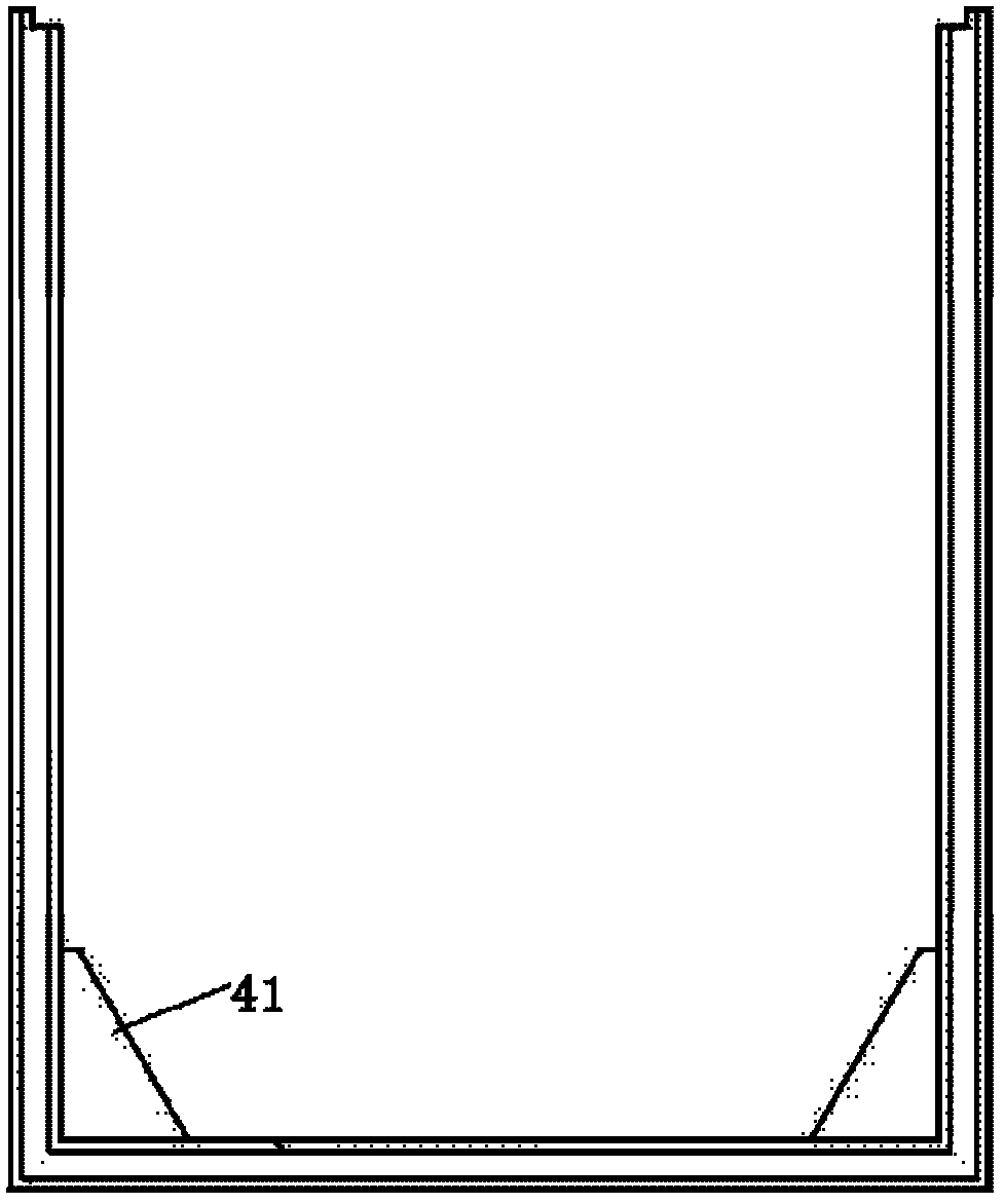
[0020] Such as figure 1 , figure 2 , image 3 As shown, an all-glass fiber reinforced plastic box-type cable trench, the cable trench is made of glass fiber reinforced plastic material, the cable trench includes a U-shaped column 4, a bottom plate 1, a side plate 2, a cover plate 5 and a bracket 3, and the U-shaped The lower end of the column 4 is fixed on the bottom plate 1, the left and right sides of the U-shaped column 4 are fixed on the side plate 2, the bracket 3 is fixed on the U-shaped column 4, and the cover plate 5 is fixed on the U-shaped column 4 upper end.

[0021] Divide the cable trench into 800mm long sections according to the distance between the cable brackets for design, the manufacturer mass-produces them, and splices them on site according to the required length. One U-shaped column 4 is arranged at a distance of 800mm. The U-shaped column 4 adopts an H-shaped slot. When installing, insert the side panels and bottom plates on both sides into the notch....


PUM


Abstract

The invention relates to a full-glass-reinforced-plastic box-type cable chute. The cable chute is made from glass reinforced plastic and comprises a U-type column, a bottom plate, side plates, a cover plate and a bracket, wherein the lower end of the U-type column is fixed on the bottom plate; the left side and the right side of the U-type column are fixed on the side plates; the bracket is fixed on the U-type column; and the cover plate is fixed at the upper end of the U-type column. Compared with the prior art, the cable chute has the advantages of short construction cycle, neat appearance of finished product, excellent electrical performance, good cable working environment and the like.

Description

technical field [0001] The invention relates to a cable trench, in particular to an all-glass reinforced plastic box-type cable trench. Background technique [0002] At present, after applying for electricity, each 10kV user must construct a user station, and a cable trench must be built in each station before equipment installation and cable laying can be carried out. The traditional cable trench mainly adopts brick-concrete structure or cast-in-place reinforced concrete structure. The construction procedures are complicated, the construction steps are cumbersome, the construction period is long, and certain construction personnel are required to carry out construction on site for a period of time during the construction period (including foundation pits) Excavation, concrete formwork erection, formwork support and steel bar binding, concrete maintenance, brick masonry, embedded parts production and pre-placement, trench finishing, etc.), the process is complicated, there a...

Claims


Application Information

Patent Timeline
18 Jul 2012
Publication
CN102593780A
IPC
H02G9/02; F16L3/06
Inventors
李峰; 孙红军