Water pump full head operation control method and controller, water pump

A work control and controller technology, which is applied in pump control, non-variable pumps, machines/engines, etc., can solve the problems of increasing production costs, affecting the service life of water pumps, and reducing the service life of water pumps, so as to avoid the waste of electric energy , Improve the degree of intelligence, and stabilize the water supply pressure

Active Publication Date: 2018-02-09
陈辉
View PDF6 Cites 0 Cited by
  • Summary
  • Abstract
  • Description
  • Claims
  • Application Information

AI Technical Summary

Problems solved by technology

[0004] At present, flow switch sensors and pressure switch sensors are commonly used. These sensors output switch signals, and the controller controls the start and stop of the water pump according to the received pressure switch signals and / or water flow switch signals. ; but due to the structural factors of this type of sensor itself, the detection accuracy is low. For example, the flow switch sensor cannot detect the water flow signal of the small flow water supply. The detection accuracy of most flow switch sensors is 50ml / s. High detection accuracy can only reach 10ml / s water flow rate, therefore, there is a control blind zone, or the frequent start and stop of the water pump will cause the service life of the water pump to be reduced; in order to obtain a better control of the water pump, a pressure switch sensor and a flow rate are generally required. The switch sensor is used at the same time, therefore, it also puts forward higher requirements on the structure of the water pump, which makes the structure of the water pump relatively complicated and increases the production cost
[0005] In addition, pressure sensors are also used. This type of sensor can detect the pressure of the water pump in real time, and output a pressure analog signal or digital signal to the controller. The controller controls the start and stop of the water pump according to the received pressure signal; currently, The water pump controlled by this method needs to set the start pressure and stop pressure after the water pump is powered on, and the water pump will automatically start and stop control according to the set start pressure and stop pressure; however, due to the incompressibility of water, from The time from the stop pressure to the start pressure is very short. Even if the pump is equipped with a pressure buffer tank, it can only prolong the time from the stop pressure to the start pressure; Seriously affect the service life of the water pump
[0006] In order to solve the frequent start and stop of the water pump, the water pump should be kept running as much as possible when using water; at present, some manufacturers use the flow switch sensor and the pressure sensor at the same time, and the control method is to set the start pressure and stop pressure of the water pump in advance , when the flow switch sensor detects the water flow signal, the water pump keeps running continuously, and when the water flow signal is disconnected, the water pump is controlled to start and stop according to the start pressure and stop pressure; this method is the same as the method of using the pressure switch sensor and the flow switch sensor at the same time The principle is the same. The key to reducing the start-stop frequency of the water pump is the accuracy of the flow switch sensor. When the water flow speed cannot be detected by the flow switch sensor, the water pump will inevitably start and stop frequently; at the same time, due to the cost of the pressure sensor relative to the pressure switch sensor Higher, which increases the production cost of the pump
[0007] In addition, due to the cost limitation of civil and agricultural water pumps, the measurement accuracy of the pressure sensor selected by the water pump manufacturer is low at present, and there is a problem of measurement reference fluctuation. During the use of the water pump, the pressure detected by the pressure sensor is different from the actual pressure of the pump The water supply pressure does not match, which will affect the water supply pressure control of the water pump

Method used


Image

  • Water pump full head operation control method and controller, water pump
  • Water pump full head operation control method and controller, water pump
  • Water pump full head operation control method and controller, water pump

Examples


Embodiment 1

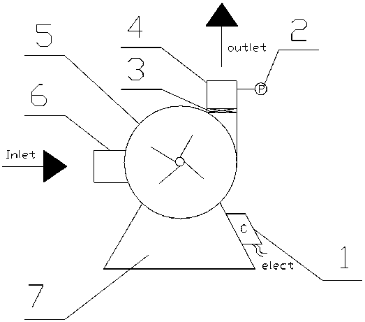
[0045] combine figure 1 and figure 2 A water pump shown includes a pump body 5, a water inlet 6, a water outlet 4, a base 7, a controller 1, a pressure sensor 2 and a check valve 3; wherein the water inlet 6 is the low pressure end of the water pump , the water outlet 4 is the high pressure end of the water pump, the water outlet 4 and the water inlet 6 are connected to the pump body; the pressure sensor 2 is used to detect the outlet pressure of the water pump, and output a pressure signal to the controller 1; The controller 1 is used to connect the external power supply and control the start and stop of the water pump; the check valve 3 is arranged at the water outlet 4 and upstream of the pressure sensor 2 .

Embodiment 2

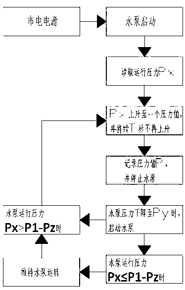
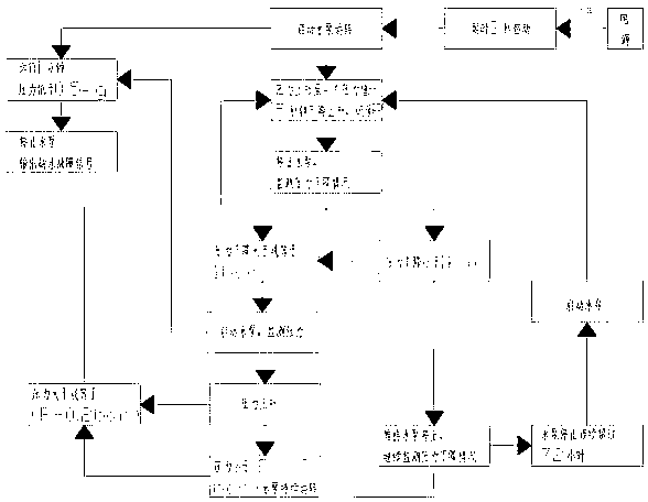
[0047] Such as image 3 and Figure 4 As shown, the water pump full lift work control method described in the above-mentioned embodiment 1 includes the following steps,

[0048] S101, start the water pump, and read the operating pressure P of the water pump x ;

[0049] S102, the operating pressure of the pump to be pumped P x Rise to a pressure value and continue for T seconds and no longer rise, then record the pressure value P, and stop the water pump; the T is 1-180;

[0050] S103, when the water pump pressure drops to P y When the water pump is started, where P y ≤P-ΔP, said ΔP>0;

[0051] S104, when the pump operating pressure P x ≤P-P z , to keep the water pump running; when the water pump running pressure P x >P-P z , then switch to step S102, where ΔP>P z >0.

[0052] Further, the P y It is pre-set; it can be set by the manufacturer when the water pump leaves the factory, or by the user when using the water pump according to the water supply demand.

[0...

Embodiment 3

[0063] combine Figure 7 The shown controller is a control circuit board that can realize any one of the water pump full-lift work control methods described in Embodiment 2 to control the water pump; the control circuit board includes:

[0064] The single-chip microcomputer 11 is used to store data and execute software programs, receive pressure signals and output signals;

[0065] The relay 31 is used to control the power on and off of the water pump and is connected to the drive module 21;

[0066] The drive module 21 is connected with the single chip microcomputer 11, and is used to control the switch of the relay 31;

[0067] The display screen 41 is connected with the single-chip microcomputer 11 for displaying pressure and fault codes;

[0068] The circuit module 51 is used for powering the single chip microcomputer 11 and the relay 31 .

[0069] The above-mentioned controller can be set on the outlet pipeline of the water pump to be controlled in conjunction with the...


PUM


Abstract

The invention provides a water pump total-lift work control method. A pressure sensor is used for detecting the running pressure of a water pump, a controller is used for automatically calculating the stop pressure of the water pump, and starting and stopping of the water pump are controlled. The total-lift work control over the water pump is achieved, the starting and stopping frequency of the water pump is reduced, and the stable water supply pressure is provided for a user. Meanwhile, a water pump water shortage detection method and a water supply system water leakage detection method are provided. The invention further provides the controller and the water pump controlled by the water pump total-lift work control method; the controller has the function of controlling the starting and stopping of the water pump through the water pump total-lift work control method; and the water pump has the beneficial effects that the starting and stopping frequency is low, the structure is simple, the water supply pressure is stable, and cost is low.

Description

technical field [0001] The present invention relates to the technical field of water pumps, in particular to the technical field of control of water pumps, and in particular to a method for controlling the full-lift work of a water pump, a controller, and a water pump. Background technique [0002] With the improvement of people's living standards and automation requirements, automatic control of water pumps is becoming more and more common, which solves the need for manual start and stop of water pumps during use, and improves efficiency; especially in civil and agricultural water supply systems, There is an increasing demand for automatically controlled water pumps. [0003] Water pumps in the civil and agricultural fields can be roughly divided into several types such as self-priming pumps, jet pumps, and submersible pumps. Intelligently control the start and stop of the water pump through the controller to achieve automatic start and stop of the water pump. [0004] At...

Claims


Application Information

Patent Timeline
Patent Type & Authority Patents(China)
IPC IPC(8): F04D15/00
CPCF04D15/00F04D15/0077
Inventor 不公告发明人
Owner 陈辉
Why Eureka
Try Eureka