Imaging magnetic field measurement and correction system for magnetic resonance device

一种磁共振、磁共振信号的技术,应用在磁共振测量、磁场的大小/方向、测量装置等方向,能够解决升高、成像磁场校正方案不够理想、成像磁场漂移等问题,达到提高成像质量的效果

Active Publication Date: 2017-02-22
SHANGHAI UNITED IMAGING HEALTHCARE
View PDF9 Cites 10 Cited by
  • Summary
  • Abstract
  • Description
  • Claims
  • Application Information

AI Technical Summary

Problems solved by technology

[0008] In addition to inhomogeneity, the stability of the imaging magnetic field itself is also an important factor to consider. The stability of the imaging magnetic field is divided into thermal stability and time stability. The gradient coil that generates the gradient imaging magnetic field dissipates a large amount of heat, which may cause In addition, the temperature of the warm hole of the magnet may also rise due to eddy currents. The increase in temperature will easily lead to changes in the magnetic permeability, which will cause the imaging magnetic field to drift and have a negative impact on the image quality. In the Chinese patent CN101427919C, a technical solution for avoiding imaging magnetic field drift by controlling temperature changes is proposed
[0009] However, the non-ideal state of the imaging magnetic field mentioned above is either to add a large number of additional hardware devices to control the non-ideal state, or to correct the image during the post-processing of the magnetic resonance. The imaging magnetic field correction scheme is not ideal enough. The image quality obtained by the resonance device is not high enough

Method used


Image

  • Imaging magnetic field measurement and correction system for magnetic resonance device
  • Imaging magnetic field measurement and correction system for magnetic resonance device
  • Imaging magnetic field measurement and correction system for magnetic resonance device

Examples


Embodiment Construction

[0067] The magnetic resonance device has high requirements on the uniformity of the magnetic field intensity, and the magnetic field intensity not only has a certain spatial distribution, but also changes with time (that is, imaging magnetic field drift occurs). The image quality output by the prior art magnetic resonance apparatus is not high enough.

[0068] In order to make the above objects, features and advantages of the present invention more comprehensible, specific embodiments of the present invention will be described in detail below in conjunction with the accompanying drawings.

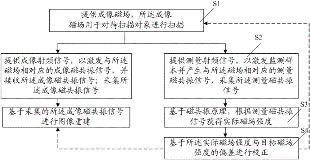
[0069] In order to solve the problems in the prior art, the present invention provides a method for measuring and correcting an imaging magnetic field in a magnetic resonance apparatus, the method comprising: providing an imaging magnetic field for scanning an object to be scanned; acquiring and The signal corresponding to the imaging magnetic field is processed; the signal is processed to ...


PUM


Abstract

The invention discloses an imaging magnetic field measurement and correction system for a magnetic resonance device. The system comprises a magnetic assembly, an acquisition unit, a processing unit, a correction unit and a control unit, wherein the magnetic assembly is used for scanning an object to be scanned; the acquisition unit is used for acquiring signals corresponding to an imaging magnetic field; the processing unit is used for processing the signals to obtain actual magnetic field intensity; the correction unit is used for correcting according to the deviation between the actual magnetic field intensity and the target magnetic field intensity; and the control unit is connected with the magnetic assembly, the acquisition unit, the processing unit and the correction unit, and is used for controlling the magnetic assembly to provide the imaging magnetic field, controlling the acquisition unit to acquire signals, controlling the processing unit to process the signals and controlling the correction unit to correct. The system can provide high-quality magnetic resonance images.

Description

[0001] This application is a divisional case of a Chinese patent application submitted to the China Patent Office on May 21, 2013, with the application number 201310191003.3, and the title of the invention is "Method and System for Imaging Magnetic Field Measurement and Correction in Magnetic Resonance Device". technical field [0002] The invention relates to magnetic resonance technology, in particular to a system for measuring and correcting an imaging magnetic field in a magnetic resonance device. Background technique [0003] Magnetic Resonance Imaging (MRI) usually consists of five parts: superconducting coils, gradient coils, radio frequency coils, computer systems and other auxiliary equipment. [0004] Wherein, the superconducting coil is the main device for generating the imaging magnetic field, and the gradient coil can provide the gradient field, and the gradient field cooperates with the main imaging magnetic field to form an imaging magnetic field (B for short) ...

Claims


Application Information

Patent Timeline
Patent Type & Authority Applications(China)
IPC IPC(8): G01R33/565G01R33/58G01R35/00G01R33/24
CPCG01R33/243G01R33/56563G01R33/58G01R35/005
Inventor 蔡昆玉张卫国张强
Owner SHANGHAI UNITED IMAGING HEALTHCARE
Why Eureka
Try Eureka