Method of measuring and correcting imaging magnetic field in magnetic resonance device and system

A technology of magnetic resonance and magnetic resonance signals, applied in the direction of measuring device, measuring electrical variables, measuring magnetic variables, etc., can solve the problems of elevation, image quality is not high enough, and the imaging magnetic field correction scheme is not ideal, and achieves the goal of improving imaging quality. Effect

Active Publication Date: 2014-12-03
SHENZHEN UNITED IMAGING HEALTHCARE CO LTD
View PDF6 Cites 13 Cited by
  • Summary
  • Abstract
  • Description
  • Claims
  • Application Information

AI Technical Summary

Problems solved by technology

[0007] In addition to inhomogeneity, the stability of the imaging magnetic field itself is also an important factor to consider. The stability of the imaging magnetic field is divided into thermal stability and time stability. The gradient coil that generates the gradient imaging magnetic field dissipates a large amount of heat, which may cause In addition, the temperature of the warm hole of the magnet may also rise due to eddy currents. The increase in temperature will easily lead to changes in the magnetic permeability, which will cause the imaging magnetic field to drift and have a negative impact on the image quality. In the Chinese patent CN101427919C, a technical solution for avoiding imaging magnetic field drift by controlling temperature changes is proposed
[0008] However, the non-ideal state of the imaging magnetic field mentioned above is either to add a large number of additional hardware devices to control the non-ideal state, or to correct the image during the post-processing of the magnetic resonance. The imaging magnetic field correction scheme is not ideal enough. The image quality obtained by the resonance device is not high enough

Method used


Image

  • Method of measuring and correcting imaging magnetic field in magnetic resonance device and system
  • Method of measuring and correcting imaging magnetic field in magnetic resonance device and system
  • Method of measuring and correcting imaging magnetic field in magnetic resonance device and system

Examples


Embodiment Construction

[0066] The magnetic resonance device has high requirements on the uniformity of the magnetic field intensity, and the magnetic field intensity not only has a certain spatial distribution, but also changes with time (that is, imaging magnetic field drift occurs). The image quality output by the prior art magnetic resonance apparatus is not high enough.

[0067] In order to make the above objects, features and advantages of the present invention more comprehensible, specific embodiments of the present invention will be described in detail below in conjunction with the accompanying drawings.

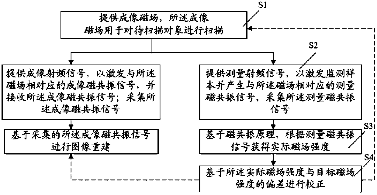
[0068] In order to solve the problems in the prior art, the present invention provides a method for measuring and correcting an imaging magnetic field in a magnetic resonance apparatus, the method comprising: providing an imaging magnetic field for scanning an object to be scanned; acquiring and The signal corresponding to the imaging magnetic field is processed; the signal is processed to ...


PUM


Abstract

A method and a system for measuring and calibrating an imaging magnetic field in a magnetic resonance apparatus are provided. The method includes: providing the imaging magnetic field, where the imaging magnetic field is adapted for scanning an object; sampling a signal corresponding to the imaging magnetic field; processing the signal to obtain an actual magnetic field intensity; and calibrating based on a difference between the actual magnetic field intensity and a target magnetic field intensity. The system includes: a magnetic component, adapted for scanning an object to be imaged; a sampling unit, adapted for sampling a signal corresponding to the imaging magnetic field; a processing unit, adapted for processing the signal to obtain an actual magnetic field intensity; a calibration unit, adapted for calibrating based on a difference between the actual magnetic field intensity and a target magnetic field intensity; and a control unit, adapted for controlling the system.

Description

technical field [0001] The invention relates to magnetic resonance technology, in particular to a method and system for measuring and correcting an imaging magnetic field in a magnetic resonance device. Background technique [0002] Magnetic Resonance Imaging (MRI) usually consists of five parts: superconducting coils, gradient coils, radio frequency coils, computer systems and other auxiliary equipment. [0003] Among them, the superconducting coil is the main device for generating the imaging magnetic field, and the gradient coil can provide the gradient field, and the gradient field cooperates with the main imaging magnetic field to form an imaging magnetic field (abbreviated as B for magnetic resonance detection). 0 field). The radio frequency coil includes a transmitting coil and a receiving coil, among which the body coil is the main transmitting coil. The transmitting coil emits radio frequency pulses to excite protons in the human body to resonate. The receiving c...

Claims


Application Information

Patent Timeline
Patent Type & Authority Applications(China)
IPC IPC(8): G01R33/389G01R33/58G01R33/387G01R33/385
CPCG01R35/005G01R33/243G01R33/56563G01R33/58
Inventor 蔡昆玉张卫国张强
Owner SHENZHEN UNITED IMAGING HEALTHCARE CO LTD
Why Eureka
Try Eureka